INTELLIGENT PARKING ASSIST SYSTEM, Diagnostic DTC:C1AEE

| DTC Code | DTC Name |
|---|---|
| C1AEE | IPA Sensor Communication Circuit |
DESCRIPTION
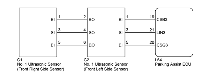
The parking assist ECU communicates with the No. 1 ultrasonic sensor (front left side sensor), and the No. 1 ultrasonic sensor (front right side sensor) via the No. 1 ultrasonic sensor (front left side sensor). This DTC is stored when the parking assist ECU judges that there is an abnormality in the communication circuit to the No. 1 ultrasonic sensor (front left side sensor) or the No. 1 ultrasonic sensor (front right side sensor) that is connected via the front left side sensor, immediately after the power switch is turned on (IG), or while the sensors are operating (neither P nor R is selected and the vehicle is not stopped).
| DTC No. | DTC Detection Condition | Trouble Area |
|---|---|---|
| C1AEE | Ultrasonic sensor communication bus failure |
|
WIRING DIAGRAM
INSPECTION PROCEDURE
Note
-
When "System initializing" message is displayed on the navigation receiver assembly after the battery terminal disconnected, correct the steering angle neutral point Click here.
-
Depending on the parts that are replaced or operations that are performed during vehicle inspection or maintenance, calibration of other systems as well as the intelligent parking assist system may be needed Click here.
PROCEDURE
-
CHECK HARNESS AND CONNECTOR (PARKING ASSIST ECU - FRONT LEFT SIDE SENSOR)
-
Disconnect the L64 connector from the parking assist ECU.
-
Disconnect the C2 connector from the No. 1 ultrasonic sensor (front left side sensor).
-
Measure the resistance according to the value(s) in the table below.
Standard Resistance Tester Connection Condition Specified Condition L64-19 (CSB3) - Body ground Always 10 kΩ or higher L64-21 (LIN3) - Body ground Always 10 kΩ or higher L64-20 (CSG3) - Body ground Always 10 kΩ or higher L64-19 (CSB3) - C2-1 (BI) Always Below 1 Ω L64-21 (LIN3) - C2-3 (SI) Always Below 1 Ω L64-20 (CSG3) - C2-5 (EI) Always Below 1 Ω
NG 
REPAIR OR REPLACE HARNESS OR CONNECTOR
OK 
-
-
CHECK NO. 1 ULTRASONIC SENSOR
-
Remove the No. 1 ultrasonic sensor (front left side sensor) Click here.
-
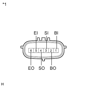
Text in Illustration *1 Component without harness connected
(No. 1 Ultrasonic Sensor (Front Left Side Sensor))
Measure the resistance according to the value(s) in the table below.
Standard Resistance Tester Connection Condition Specified Condition 1 (BI) - 5 (EI) Always 10 kΩ or higher 1 (BI) - 2 (BO) Always 10 kΩ or higher 3 (SI) - 4 (SO) Always Below 1 Ω 5 (EI) - 6 (EO) Always Below 1 Ω
NG
REPLACE NO. 1 ULTRASONIC SENSOR (FRONT LEFT SIDE SENSOR) Click here
OK
-
-
CHECK HARNESS AND CONNECTOR (FRONT LEFT SIDE SENSOR - FRONT RIGHT SIDE SENSOR)
-
Disconnect the C2 connector from the No. 1 ultrasonic sensor (front left side sensor).
-
Disconnect the C1 connector from the No. 1 ultrasonic sensor (front right side sensor).
-
Measure the resistance according to the value(s) in the table below.
Standard Resistance Tester Connection Condition Specified Condition C2-2 (BO) - C1-1 (BI) Always Below 1 Ω C2-4 (SO) - C1-3 (SI) Always Below 1 Ω C2-6 (EO) - C1-5 (EI) Always Below 1 Ω C2-2 (BO) - Body ground Always 10 kΩ or higher C2-4 (SO) - Body ground Always 10 kΩ or higher C2-6 (EO) - Body ground Always 10 kΩ or higher
NG
REPAIR OR REPLACE HARNESS OR CONNECTOR
OK
-
-
REPLACE NO. 1 ULTRASONIC SENSOR (FRONT LEFT SIDE SENSOR)
-
Replace the No. 1 ultrasonic sensor (front left side sensor) with a normally functioning sensor Click here.
NEXT
-
-
CHECK DTC OUTPUT
-
Clear the DTCs Click here.
-
Check for DTCs Click here.
Result Result Proceed to DTC C1AEE is output A No DTC is output B
B
END (FRONT LEFT SIDE SENSOR WAS DEFECTIVE)
A
-
-
REPLACE NO. 1 ULTRASONIC SENSOR (FRONT RIGHT SIDE SENSOR)
-
Replace the No. 1 ultrasonic sensor (front right side sensor) with a normally functioning sensor Click here.
NEXT
-
-
CHECK DTC OUTPUT
-
Clear the DTCs Click here.
-
Check for DTCs Click here.
Result Result Proceed to DTC C1AEE is output A No DTC is output B
B
END (FRONT RIGHT SIDE SENSOR WAS DEFECTIVE)
A 
REPLACE PARKING ASSIST ECU Click here
-