INTELLIGENT PARKING ASSIST SYSTEM "CHK" message(s) are displayed on the SIGNAL CHECK screen.
DESCRIPTION
On the SIGNAL CHECK screen, it is possible to check if the state of signals sent to the parking assist ECU is normal Click here.
Tech Tips
-
On the SIGNAL CHECK screen, "OK" (blue) is displayed for items with a normal inspection result or input state.
-
On the SIGNAL CHECK screen, "CHK" (red) is displayed for items with an abnormal inspection result or input state.
-
Displayed items may differ depending on vehicle specifications.
| Item | Signal Input Method | Detail | DTC Output when Abnormal Result is Displayed | Signal Receiver |
|---|---|---|---|---|
| CAN | CAN communication | CAN communication condition | DTC is output | - |
| IPA SW | Vehicle wire harness | Parking assist pre support switch assembly signal input | DTC is not output | Parking assist pre support switch assembly |
| EPS | - | Brush information for EPS currently selected at individual setting screen | DTC is not output | - |
| HT SENS | Vehicle wire harness | Height control sensor signal input | DTC is output | Rear height control sensor sub-assembly RH |
| HT INIT | - | Height control sensor vehicle height difference setting status | DTC is output | - |
| HANDLE | CAN communication | CAN communication condition | DTC is output | - |
| DEST | CAN communication | CAN communication condition | DTC is output | - |
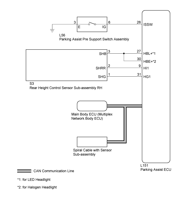
WIRING DIAGRAM
INSPECTION PROCEDURE
Note
-
When the "System initializing" message is displayed on the navigation ECU sub-assembly after the auxiliary battery cable has been disconnected, correct the steering angle neutral point Click here.
-
Depending on the parts that are replaced or operations that are performed during vehicle inspection or maintenance, calibration of other systems as well as the intelligent parking assist system may be needed Click here.
PROCEDURE
-
CHECK DISPLAY CHECK MODE
-
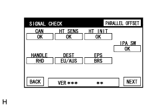
Check which items display "CHK" (red) on the SIGNAL CHECK screen.
Result Result Proceed to "IPA SW" displays "CHK" (red). A "HT INIT" displays "CHK" (red). B Both "HT SENS" and "HT INIT" display "CHK" (red). C Any of "CAN", "HANDLE", and "DEST" displays "CHK" (red). C "EPS" displays "CHK" (red). D
B 
ADJUST HEIGHT CONTROL SENSOR VEHICLE HEIGHT DIFFERENCE SETTING Click here
C
CHECK DTC OUTPUT Click here
D
SET EPS BRUSH TYPE Click here
A 
-
-
CHECK HARNESS AND CONNECTOR (PARKING ASSIST ECU - PARKING ASSIST PRE SUPPORT SWITCH ASSEMBLY)
-
Disconnect the L151 connector from the parking assist ECU.
-
Disconnect the L56 connector from the parking assist pre support switch assembly.
-
Measure the resistance according to the value(s) in the table below.
Standard Resistance Tester Connection Condition Specified Condition L151-26 (ISSW) - L56-6 (IG) Always Below 1 Ω
NG
REPAIR OR REPLACE HARNESS OR CONNECTOR
OK
-
-
INSPECT PARKING ASSIST PRE SUPPORT SWITCH ASSEMBLY
-
Remove the parking assist pre support switch assembly Click here.
-
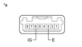
Text in Illustration *a Component without harness connected
(Parking Assist Pre Support Switch Assembly)
Measure the resistance according to the value(s) in the table below.
Standard Resistance Tester Connection Condition Specified Condition 3 (E) - 6 (IG) Parking assist pre support switch assembly pushed Below 1 Ω Parking assist pre support switch assembly not pushed 10 kΩ or higher
NG
REPLACE PARKING ASSIST PRE SUPPORT SWITCH ASSEMBLY Click here
OK 
REPLACE PARKING ASSIST ECU Click here
-