INTELLIGENT PARKING ASSIST SYSTEM, Diagnostic DTC:C1627

| DTC Code | DTC Name |
|---|---|
| C1627 | Vehicle Height Sensor Voltage is Low or High |
DESCRIPTION
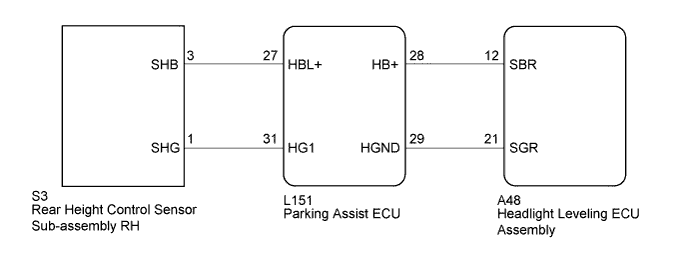
The rear height control sensor sub-assembly RH and headlight leveling ECU assembly (for LED headlight) are connected to the parking assist ECU. The parking assist ECU shares the vehicle height signals received from the rear height control sensor sub-assembly RH with the lighting system (auto leveling). The headlight leveling ECU assembly (for LED headlight) supplies power to the rear height control sensor sub-assembly RH via the parking assist ECU. This DTC is stored when the parking assist ECU judges that the power supply voltage for the rear height control sensor sub-assembly RH is not normal.
| DTC No. | DTC Detection Condition | Trouble Area |
|---|---|---|
| C1627 |
|
|
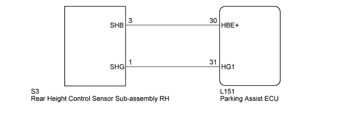
WIRING DIAGRAM
-
for LED Headlight
-
for Halogen Headlight
INSPECTION PROCEDURE
Note
-
When the "System initializing" message is displayed on the navigation ECU sub-assembly after the auxiliary battery cable has been disconnected, correct the steering angle neutral point Click here.
-
Depending on the parts that are replaced or operations that are performed during vehicle inspection or maintenance, calibration of other systems as well as the intelligent parking assist system may be needed Click here.
-
When the headlight leveling ECU assembly (for LED headlight) is replaced, perform initialization for the lighting system Click here
-
If initialization is necessary while performing an inspection, perform initialization first and then proceed to the next step.
PROCEDURE
-
CHECK DTC OUTPUT
-
Clear the DTCs Click here.
-
Check for DTCs Click here.
Result Result Proceed to DTC C1627 is output A DTCs are not output B Tech Tips
-
If the power source voltage output by the headlight leveling ECU assembly (for LED headlight) is abnormal, the headlight leveling warning light may come on.
-
If the DTCs are not output again when rechecking for DTCs, it may have been stored due to a temporarily abnormal voltage.
-
If DTC C1627 is output frequently, duplicate the problem symptoms and perform the inspection again, even though the DTCs are not output when rechecking for DTCs Click here.
-
B 
USE SIMULATION METHOD TO CHECK Click here
A 
-
-
CHECK VEHICLE SPECIFICATION
-
Check vehicle specifications.
Result Result Proceed to for LED Headlight A for Halogen Headlight B
B 
CHECK HARNESS AND CONNECTOR (REAR HEIGHT CONTROL SENSOR SUB-ASSEMBLY RH - PARKING ASSIST ECU) Click here
A
-
-
CHECK HARNESS AND CONNECTOR (HEADLIGHT LEVELING ECU ASSEMBLY - PARKING ASSIST ECU)
-
Disconnect the A48 connector from the headlight leveling ECU assembly.
-
Disconnect the L151 connector from the parking assist ECU.
-
Measure the resistance according to the value(s) in the table below.
Standard Resistance Tester Connection Condition Specified Condition A48-12 (SBR) - Body ground Always 10 kΩ or higher A48-21 (SGR) - Body ground Always 10 kΩ or higher A48-12 (SBR) - L151-28 (HB+) Always Below 1 Ω A48-21 (SGR) - L151-29 (HGND) Always Below 1 Ω
NG
REPAIR OR REPLACE HARNESS OR CONNECTOR
OK
-
-
CHECK HEADLIGHT LEVELING ECU ASSEMBLY
-
Reconnect the A48 connector to the headlight leveling ECU assembly.
-
Disconnect the L151 connector from the parking assist ECU.
-
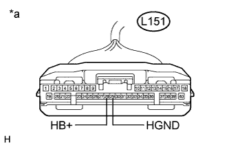
Text in Illustration *a Front view of wire harness connector
(to Parking Assist ECU)
Measure the voltage according to the value(s) in the table below.
Standard Voltage Tester Connection Condition Specified Condition L151-28 (HB+) - L151-29 (HGND) Power switch on (IG) 4.75 to 5.25 V
NG
REPLACE HEADLIGHT LEVELING ECU ASSEMBLY Click here
OK
-
-
CHECK HARNESS AND CONNECTOR (REAR HEIGHT CONTROL SENSOR SUB-ASSEMBLY RH - PARKING ASSIST ECU)
-
Disconnect the L151 connector from the parking assist ECU.
-
Disconnect the S3 connector from the rear height control sensor sub-assembly RH.
-
Measure the resistance according to the value(s) in the table below.
Standard Resistance Tester Connection Condition Specified Condition L151-27 (HBL+) - Body ground Always 10 kΩ or higher L151-31 (HG1) - Body ground Always 10 kΩ or higher L151-27 (HBL+) - S3-3 (SHB) Always Below 1 Ω L151-31 (HG1) - S3-1 (SHG) Always Below 1 Ω Result Result Proceed to NG A OK B
B
CHECK REAR HEIGHT CONTROL SENSOR SUB-ASSEMBLY RH Click here
A 
REPAIR OR REPLACE HARNESS OR CONNECTOR
-
-
CHECK HARNESS AND CONNECTOR (REAR HEIGHT CONTROL SENSOR SUB-ASSEMBLY RH - PARKING ASSIST ECU)
-
Disconnect the L151 connector from the parking assist ECU.
-
Disconnect the S3 connector from the rear height control sensor sub-assembly RH.
-
Measure the resistance according to the value(s) in the table below.
Standard Resistance Tester Connection Condition Specified Condition L151-30 (HBE+) - Body ground Always 10 kΩ or higher L151-31 (HG1) - Body ground Always 10 kΩ or higher L151-30 (HBE+) - S3-3 (SHB) Always Below 1 Ω L151-31 (HG1) - S3-1 (SHG) Always Below 1 Ω
NG
REPAIR OR REPLACE HARNESS OR CONNECTOR
OK
-
-
CHECK REAR HEIGHT CONTROL SENSOR SUB-ASSEMBLY RH
-
Reconnect the L151 connector to the parking assist ECU.
-
Disconnect the S3 connector from the rear height control sensor sub-assembly RH.
-
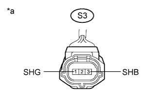
Text in Illustration *a Front view of wire harness connector
(to Rear Height Control Sensor Sub-assembly RH)
Measure the voltage according to the value(s) in the table below.
Standard Voltage Tester Connection Condition Specified Condition S3-3 (SHB) - S3-1 (SHG) Power switch on (IG) 4.75 to 5.25 V
NG
REPLACE PARKING ASSIST ECU Click here
OK
REPLACE REAR HEIGHT CONTROL SENSOR SUB-ASSEMBLY RH Click here
-