INTELLIGENT PARKING ASSIST SYSTEM CALIBRATION

-
ADJUST INTELLIGENT PARKING ASSIST SYSTEM
-
This intelligent parking assist system can be set from the diagnostic screen of the navigation receiver assembly.
-
If the following operations are performed, it is necessary to perform adjustments and checks on the diagnostic screen.
Part Name Operation Adjustment Item Proceed to Spiral with sensor cable sub-assembly
-
Removal and installation of the spiral with sensor cable sub-assembly
-
Removal and installation of the connector of the spiral with sensor cable sub-assembly
Steering angle neutral point Steering angle setting Spiral with sensor cable sub-assembly Replacement Steering angle neutral point Steering angle setting Parking assist ECU Replacement Parking assist ECU initialization Step 2 Suspension, tires, etc. The vehicle height changes because of suspension or tire replacement Height control sensor vehicle height difference (Height set) Step 3 Rear television camera optical axis (Camera position setting) Step 4 Rear television camera assembly
-
Replacement
-
Installation angle of the rear television camera changes because of the removal and installation of the rear television camera, etc.
Rear television camera optical axis (Camera position setting) Step 4 Rear height control sensor sub-assembly RH
-
Replacement
-
Installation position of the rear height control sensor sub-assembly RH changes because of the removal and installation of the rear height control sensor sub-assembly RH
Height control sensor vehicle height difference (Height set) Step 3 Rear television camera optical axis (Camera position setting) Step 4 Lighting system initialization Rear bumper cover
-
Replacement
-
Installation position of the rear bumper cover changes because of the removal and installation of the rear bumper cover
Rear bumper position (BUMPER) Step 5 Tech Tips
The adjustment values stored while performing intelligent parking assist system calibration are stored in the parking assist ECU.
-
-
-
PARKING ASSIST ECU INITIALIZATION
Tech Tips
Be sure to check for DTCs before performing this procedure Click here.
-
Preparation for adjustment
-
Park the vehicle on the flat place with the steering wheel centered.
Tech Tips
Before parking the vehicle, be sure to move the vehicle forward and in reverse to check that the tires are facing straight ahead with the steering wheel centered.
-
Adjust the tire pressure to the specification.
-
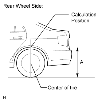
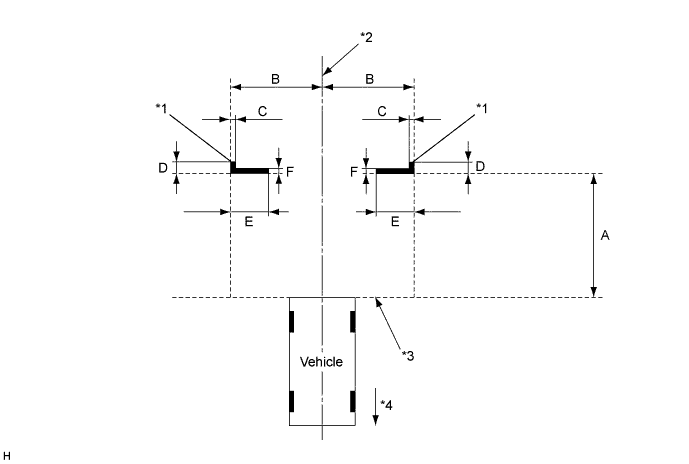
Text in Illustration *1 Target Bar for Camera Adjustment *2 Vehicle Center *3 Bumper Edge *4 Front Side Measure the distance A between the ground and the edge of a rear wheel arch.
-
Calculate the difference between the distance A and the standard height below.
Tech Tips
Subtract the standard value from the measured value to get the standard height. When the measured value is 707 mm: 707 - 697 = +10 (standard height is +10 mm).
-
Set a target bar for optical axis adjustment of the rear television camera.
Tech Tips
Only when adjusting the optical axis of the camera, create a target bar for adjustment.
Tech Tips
Check the tape color on the navigation receiver assembly and choose a tape color which can be easily seen.
-
-
Start diagnostic mode Click here.
Note
Mode setting must be carried out with the hybrid system started. Apply the parking brake, depress the brake pedal, push the P position switch, and ensure that the vehicle is not moving.
Tech Tips
The displayed items may differ depending on vehicle specifications.
-
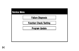
Select "Function Check/Setting" on the Service Menu screen.
-
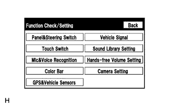
Select "Camera Setting" on the Function Check/Setting screen.
-
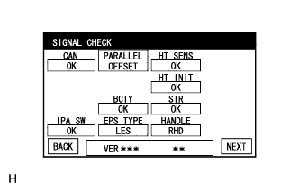
Check that "CHK" (red) is not displayed on the SIGNAL CHECK screen.
Note
-
When "CHK" (red) is displayed for any items except "EPS TYPE" on the SIGNAL CHECK screen, selecting "NEXT" will not change the screen to the INDIVIDUAL SETTING screen.
-
When "CHK" (red) is displayed for any items except "EPS TYPE" and "HT INIT" on the SIGNAL CHECK screen, perform inspections using the SIGNAL CHECK screen Click here.
Tech Tips
When the screen is not change to the HEIGHT SET screen, check for DTCs and perform troubleshooting based on the output DTCs Click here.
-
-
-
HEIGHT SET
Note
-
The height control sensor vehicle height difference setting must be performed on the flat place.
-
Before performing the television camera optical axis adjustment, the height control sensor vehicle height difference must be performed in the "HEIGHT SET" screen.
-
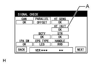
Select the indicator "A" for "HT INIT" on the SIGNAL CHECK screen.
-
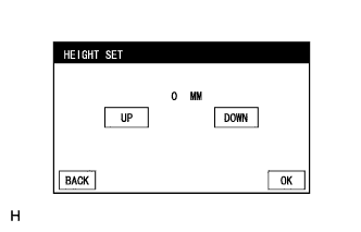
Press "UP" and "DOWN" to input the calculated difference.
Tech Tips
-
A positive value is indicated in green and a negative value is indicated in red.
-
When a value is "10 MM" in green, it means +10 mm.
-
Available setting range: -102 mm to +102 mm (can be adjusted in 1 mm increments)
-
-
After inputting the calculated difference, select "OK". The height control sensor vehicle height difference setting will be recorded.
Tech Tips
-
When "OK" is selected, a beep will sound to confirm that the height difference set values have been stored.
-
The setting value will not be stored unless "OK" is selected.
-
Until a beep finishes sounding, the adjustment values are not stored.
-
When "BACK" is selected, the screen changes to SIGNAL CHECK screen without storing the set values.
-
Press "OK" with the vehicle in the same condition as when the vehicle height was measured.
-
If a person was in the driver seat when the vehicle height was measured, press "OK" with the same person in the driver seat.
-
On the "SIGNAL CHECK" screen, check that the indicator "A" for "HT INIT" is "OK" (blue).
-
-
Select "NEXT" on the SIGNAL CHECK screen.
-
-
INDIVIDUAL SETTING
-
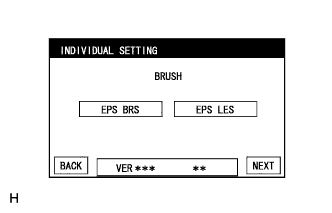
Select the "EPS LES" on the INDIVIDUAL SETTING screen.
Tech Tips
-
Selected EPS brush specification is indicated in blue.
-
EPS brush refers to the type of motor used for the EPS system (with brushes or brushless).
-
-
Select "NEXT" on the INDIVIDUAL SETTING screen.
-
-
CAMERA POSITION SETTING (ROLL ANGLE ADJUSTMENT)
Note
Before performing the television camera optical axis adjustment, the height control sensor vehicle height difference setting must be performed in the "HEIGHT SET" screen.
Tech Tips
-
When the back door is open, the "Back door is open. Do not use the rear view monitor when the back door is not completely closed." message will be displayed and television camera optical axis adjustment will not be possible.
-
If the "Back door is open. Do not use the rear view monitor when the back door is not completely closed." message is displayed even when the back door is closed, perform inspections according to Problem Symptoms Table (A back door open warning message is displayed even after back door is closed) Click here.
-
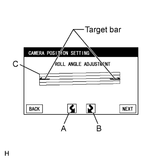
Select switches A and B to rotate C so that it is parallel to the target adjustment bar.
-
Select "NEXT" on the CAMERA POSITION SETTING (ROLL ANGLE ADJUSTMENT) screen.
-
-
CAMERA POSITION SETTING (VERTICAL AND HORIZONTAL POSITION ADJUSTMENT)
-
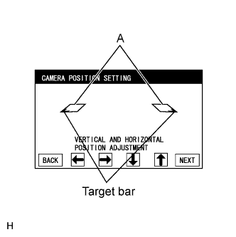
By pressing the left and right, and up and down switches, move the parallelograms (A) vertically and horizontally so that the corners of the target bars (C) and the corners of the parallelograms (A) match.
Note
-
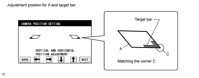
If the left and right parallelograms (A) and target bars do not match completely, just match the corners of the target bars (C) with the corners of the parallelograms (A).
-
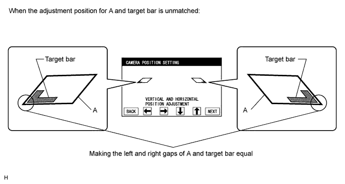
If the left and right parallelograms (A) and the corners of the target bars (C) do not match, make the gaps between each parallelogram (A) and the target bars equal on the left and right sides.
-
-
Select "NEXT" on the CAMERA POSITION SETTING (VERTICAL AND HORIZONTAL POSITION ADJUSTMENT) screen.
-
-
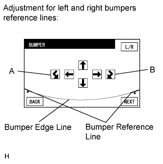
BUMPER (SIMULTANEOUS ADJUSTMENT)
-
By pressing the left and right, up and down and A and B switches, move the bumper reference lines vertically and horizontally or rotate them so that the bumper reference lines overlap or contact the bumper edge line.
Tech Tips
If the bumper reference lines do not overlap or contact the bumper edge line, select "L/R" to perform bumper reference line position adjustment (individual adjustment).
-
When the bumper reference lines and bumper edge line overlap or contact each other, select "NEXT".
-
-
LEFT BUMPER
-
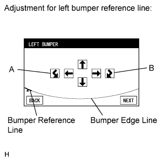
By pressing the left and right, up and down and A and B switches, move the left bumper reference line vertically and horizontally or rotate it so that the bumper reference lines overlap or contact the bumper edge line.
Tech Tips
When the left bumper reference line overlaps or contacts the bumper edge line in the bumper reference line position adjustment (individual adjustment) step, select "NEXT".
-
Select "NEXT" on the LEFT BUMPER screen.
-
-
RIGHT BUMPER
-
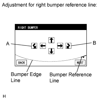
By pressing the left and right, up and down and A and B switches, move the right bumper reference line vertically and horizontally or rotate it so that the bumper reference lines overlap or contact the bumper edge line.
Tech Tips
When the right bumper reference line overlaps or contacts the bumper edge line in the bumper reference line position adjustment (individual adjustment) step, select "NEXT".
-
Select "NEXT" on the RIGHT BUMPER screen.
-
-
VERIFY MODE
-
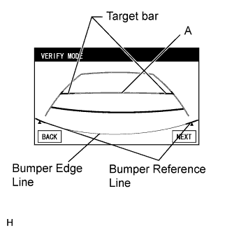
Check that line A (indicating 1100 mm forward from the bumper edge) and the target bars are nearly overlapping and that the bumper reference lines and bumper edge line are nearly overlapping. With the steering wheel centered, check that the predicted path line is straight (overlapping the vehicle width extension lines).
-
Selecting "NEXT" on the VERIFY MODE screen will be completed the camera aiming adjustment.
Tech Tips
-
When "NEXT" is selected, a beep will sound to confirm that the camera aiming adjustment values have been stored.
-
The adjustment value will not be stored unless "NEXT" is selected.
-
Until a beep finishes sounding, the adjustment values are not stored.
-
-
-
STEERING ANGLE SETTING
-
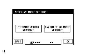
Perform the STEERING CENTER MEMORIZE operation.
-
Check that the steering wheel is centered, and then select "STEERING CENTER MEMORIZE".
Tech Tips
When performing removal and installation, or replacement of the television camera, steering angle adjustment is not required.
-
-
Perform the MAX STEERING ANGLE MEMORIZE operation.
-
After adjusting the steering angle neutral point, turn the steering wheel to the left and right lock positions and select "MAX STEERING ANGLE MEMORIZE". The maximum steering angle is then stored and the screen changes to the Function Check/Setting screen.
Tech Tips
-
It is also possible to start by initially turning the steering to the right side.
-
When "MAX STEERING ANGLE MEMORIZE" is selected, a beep will sound to confirm that the steering adjustment values have been stored.
-
Until a beep finishes sounding, the adjustment values are not stored.
-
The adjustment value will not be stored unless "MAX STEERING ANGLE MEMORIZE" is selected after turning the steering wheel side to side.
-
When "BACK" is selected, the screen changes to VERIFY MODE without storing the set values.
-
The "OK" button does not respond until the system stores the steering angle neutral point and maximum steering angle.
-
Even if no DTCs are detected, selecting "MAX STEERING ANGLE MEMORIZE" may not cause the adjustment value to be stored if the steering sensor is malfunctioning.
-
If selecting "MAX STEERING ANGLE MEMORIZE" does not cause the adjustment value to be stored after adjusting the steering angle, replace the spiral with sensor cable sub-assembly Click here.
-
-
-
-
Finish diagnostic mode Click here.
-
Confirm steering angle adjustment.
Tech Tips
If the steering angle has been adjusted, confirm the steering angle adjustment on the intelligent parking assist screen after finishing diagnosis mode.
-
Check on the intelligent parking assist screen that the predicted path line moves until the steering wheel is fully turned to either the left or right.
Tech Tips
If the predicted path line stops moving before the steering wheel is fully turned to either the left or right, the steering angle adjustment values have not been stored correctly. In this case, perform "STEERING CENTER MEMORIZE" and "MAX STEERING ANGLE MEMORIZE" again.
-
-
-
HEIGHT CONTROL SENSOR VEHICLE HEIGHT DIFFERENCE SETTING (HEIGHT SET)
-
Preparation for adjustment
Tech Tips
-
The height control sensor vehicle height difference setting must be performed on the flat place.
-
Before performing the television camera optical axis adjustment, the height control sensor vehicle height difference setting must be performed in the "HEIGHT SET" screen.
-
Adjust the tire pressure to the specification.
-
Measure the distance A between the ground and the edge of a rear wheel arch.
-
Calculate the difference between the distance A and the standard height below.
Tech Tips
Subtract the standard value from the measured value to get the standard height. When the measured value is 707 mm: 707 - 697 = +10 (standard height is +10 mm).
-
-
Start diagnostic mode.
Note
Mode setting must be carried out with the hybrid system started. Apply the parking brake, depress the brake pedal, push the P position switch, and ensure that the vehicle is not moving.
Tech Tips
The displayed items may differ depending on vehicle specifications.
-
Select "Function Check/Setting" on the Service Menu screen.
-
Select "Camera Setting" on the Function Check/Setting screen.
-
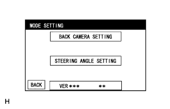
Select "BACK CAMERA SETTING" on the MODE SETTING screen.
Tech Tips
To select a grayed out item, select and hold the item for 2 seconds or more.
-
Select the indicator "A" for "HT INIT" on the SIGNAL CHECK screen.
Tech Tips
-
When "CHK" (red) is displayed for any items except "EPS TYPE" and "HT INIT" on the SIGNAL CHECK screen, perform inspections using the SIGNAL CHECK screen.
-
When the screen is not change to the HEIGHT SET screen, check for DTCs and perform troubleshooting based on the output DTCs.
-
-
-
HEIGHT SET
-
Press "UP" and "DOWN" to input the calculated difference.
Tech Tips
-
A positive value is indicated in green and a negative value is indicated in red.
-
When a value is "10 MM" in green, it means +10 mm.
-
Available setting range: -102 mm to +102 mm (can be adjusted in 1 mm increments)
-
-
After inputting the calculated difference, select "OK". The height control sensor vehicle height difference setting will be recorded.
Tech Tips
-
When "OK" is selected, a beep will sound to confirm that the height difference set values have been stored.
-
The setting value will not be stored unless "OK" is selected.
-
Until a beep finishes sounding, the adjustment values are not stored.
-
When "BACK" is selected, the screen changes to SIGNAL CHECK screen without storing the set values.
-
Press "OK" with the vehicle in the same condition as when the vehicle height was measured.
-
If a person was in the driver seat when the vehicle height was measured, press "OK" with the same person in the driver seat.
-
On the "SIGNAL CHECK" screen, check that the indicator "A" for "HT INIT" is "OK" (blue).
-
-
-
Finish diagnostic mode.
-
-
REAR TELEVISION CAMERA OPTICAL AXIS ADJUSTMENT (CAMERA POSITION SETTING)
Tech Tips
Be sure to check for DTCs before performing this procedure.
-
Preparation for adjustment
Note
Before performing the television camera optical axis adjustment, the height control sensor vehicle height difference setting must be performed in the "HEIGHT SET" screen.
-
Park the vehicle with the steering wheel centered.
Tech Tips
Before parking the vehicle, be sure to move the vehicle forward and in reverse to check that the tires are facing straight ahead with the steering wheel centered.
-
Adjust the tire pressure to the specification.
-
Set a target bar for optical axis adjustment of the rear television camera.
Tech Tips
Only when adjusting the optical axis of the camera, create a target bar for adjustment.
Text in Illustration *1 Target Bar for Camera Adjustment *2 Vehicle Center *3 Bumper Edge *4 Front Side Tech Tips
Check the tape color on the navigation receiver assembly and choose a tape color which can be easily seen.
-
-
Start diagnostic mode.
Note
Mode setting must be carried out with the hybrid system started. Apply the parking brake, depress the brake pedal, push the P position switch, and ensure that the vehicle is not moving.
Tech Tips
The displayed items may differ depending on vehicle specifications.
-
Select "Function Check/Setting" on the "Service Menu" screen.
-
Select "Camera Setting" on the Function Check/Setting screen.
-
Select "BACK CAMERA SETTING" on the MODE SETTING screen.
Tech Tips
To select a grayed out item, select and hold the item for 2 seconds or more.
-
Select "NEXT" on the SIGNAL CHECK screen.
Note
-
When "CHK" (red) is displayed for any items except "EPS TYPE" on the SIGNAL CHECK screen, selecting "NEXT" will not change the screen to the INDIVIDUAL SETTING screen.
-
When "CHK" (red) is displayed for any items except "EPS TYPE" and "HT INIT" on the SIGNAL CHECK screen, perform inspections using the SIGNAL CHECK screen.
-
-
-
INDIVIDUAL SETTING
-
Select the "EPS LES" on the INDIVIDUAL SETTING screen.
Tech Tips
-
Selected EPS brush specification is indicated in blue.
-
EPS brush refers to the type of motor used for the EPS system (with brushes or brushless).
Note
-
If the selected EPS brush specification does not match the vehicle specification, select the one that matches the vehicle specification.
-
When the EPS brush specification is modified, steering angle setting is required Click here.
-
-
Select "NEXT" on the INDIVIDUAL SETTING screen.
Tech Tips
-
The INDIVIDUAL SETTING screen will not be displayed when "BACK" is selected after switching to the CAMERA POSITION SETTING (ROLL ANGLE ADJUSTMENT) screen.
-
To display the INDIVIDUAL SETTING screen again, go back to the Function Check/Setting screen, select "Camera Setting" and repeat the steps.
-
-
-
CAMERA POSITION SETTING (ROLL ANGLE ADJUSTMENT)
Note
Before performing the television camera optical axis adjustment, the height control sensor vehicle height difference setting must be performed in the "HEIGHT SET" screen.
Tech Tips
-
When the back door is open, the "Back door is open. Do not use the rear view monitor when the back door is not completely closed." message will be displayed and television camera optical axis adjustment will not be possible.
-
If the "Back door is open. Do not use the rear view monitor when the back door is not completely closed." message is displayed even when the back door is closed, perform inspections according to Problem Symptoms Table (A back door open warning message is displayed even after back door is closed).
-
Select switches A and B to rotate C so that it is parallel to the target adjustment bar.
-
Select "NEXT" on the CAMERA POSITION SETTING (ROLL ANGLE ADJUSTMENT) screen.
-
-
CAMERA POSITION SETTING (VERTICAL AND HORIZONTAL POSITION ADJUSTMENT)
-
By pressing the left and right, and up and down switches, move the parallelograms (A) vertically and horizontally so that the corners of the target bars (C) and the corners of the parallelograms (A) match.
Note
-
If the left and right parallelograms (A) and target bars do not match completely, just match the corners of the target bars (C) with the corners of the parallelograms (A).
-
If the left and right parallelograms (A) and the corners of the target bars (C) do not match, make the gaps between each parallelogram (A) and the target bars equal on the left and right sides.
-
-
Select "NEXT" on the CAMERA POSITION SETTING (VERTICAL AND HORIZONTAL POSITION ADJUSTMENT) screen.
-
-
BUMPER (SIMULTANEOUS ADJUSTMENT)
-
By pressing the left and right, up and down and A and B switches, move the bumper reference lines vertically and horizontally or rotate them so that the bumper reference lines overlap or contact the bumper edge line.
Tech Tips
If the bumper reference lines do not overlap or contact the bumper edge line, select "L/R" to perform bumper reference line position adjustment (individual adjustment).
-
When the bumper reference lines and bumper edge line overlap or contact each other, select "NEXT".
-
-
LEFT BUMPER
-
By pressing the left and right, up and down and A and B switches, move the left bumper reference line vertically and horizontally or rotate it so that the bumper reference lines overlap or contact the bumper edge line.
Tech Tips
When the left bumper reference line overlaps or contacts the bumper edge line in the bumper reference line position adjustment (individual adjustment) step, select "NEXT".
-
Select "NEXT" on the LEFT BUMPER screen.
-
-
RIGHT BUMPER
-
By pressing the left and right, up and down and A and B switches, move the right bumper reference line vertically and horizontally or rotate it so that the bumper reference lines overlap or contact the bumper edge line.
Tech Tips
When the right bumper reference line overlaps or contacts the bumper edge line in the bumper reference line position adjustment (individual adjustment) step, select "NEXT".
-
Select "NEXT" on the RIGHT BUMPER screen.
-
-
VERIFY MODE
-
Check that line A (indicating 1100 mm forward from the bumper edge) and the target bars are nearly overlapping and that the bumper reference lines and bumper edge line are nearly overlapping. With the steering wheel centered, check that the predicted path line is straight (overlapping the vehicle width extension lines).
-
Selecting "NEXT" on the VERIFY MODE screen will be completed the camera aiming adjustment.
Tech Tips
-
When "NEXT" is selected, a beep will sound to confirm that the camera aiming adjustment values have been stored.
-
The adjustment value will not be stored unless "NEXT" is selected.
-
Until a beep finishes sounding, the adjustment values are not stored.
-
-
-
Finish diagnostic mode.
-
-
BUMPER POSITION SETTING
-
Start diagnostic mode.
Note
Mode setting must be carried out with the hybrid system started. Apply the parking brake, depress the brake pedal, push the P position switch, and ensure that the vehicle is not moving.
Tech Tips
The displayed items may differ depending on vehicle specifications.
-
Select "Function Check/Setting" on the "Service Menu" screen.
-
Select "Camera Setting" on the Function Check/Setting screen.
-
Select "BACK CAMERA SETTING" on the MODE SETTING screen.
Tech Tips
To select a grayed out item, select and hold the item for 2 seconds or more.
-
Select "NEXT" on the SIGNAL CHECK screen.
Note
-
When "CHK" (red) is displayed for any items except "EPS TYPE" on the SIGNAL CHECK screen, selecting "NEXT" will not change the screen to the INDIVIDUAL SETTING screen.
-
When "CHK" (red) is displayed for any items except "EPS TYPE" and "HT INIT" on the SIGNAL CHECK screen, perform inspections using the SIGNAL CHECK screen.
-
-
-
INDIVIDUAL SETTING
-
Select the "EPS LES" on the INDIVIDUAL SETTING screen.
Tech Tips
-
Selected EPS brush specification is indicated in blue.
-
EPS brush refers to the type of motor used for the EPS system (with brushes or brushless).
Note
-
If the selected EPS brush specification does not match the vehicle specification, select the one that matches the vehicle specification.
-
When the EPS brush specification is modified, steering angle setting is required.
-
-
Select "NEXT" on the INDIVIDUAL SETTING screen.
Tech Tips
-
The INDIVIDUAL SETTING screen will not be displayed when "BACK" is selected after switching to the CAMERA POSITION SETTING (ROLL ANGLE ADJUSTMENT) screen.
-
To display the INDIVIDUAL SETTING screen again, go back to the Function Check/Setting screen, select "Camera Setting" and repeat the steps.
-
-
-
CAMERA POSITION SETTING (ROLL ANGLE ADJUSTMENT)
Tech Tips
-
When only bumper reference line position adjustment is required after servicing the vehicle, CAMERA POSITION SETTING (ROLL ANGLE ADJUSTMENT) is unnecessary. Select "NEXT".
-
When the back door is open, the "Back door is open. Do not use the rear view monitor when the back door is not completely closed." message will be displayed and television camera optical axis adjustment will not be possible.
-
If the "Back door is open. Do not use the rear view monitor when the back door is not completely closed." message is displayed even when the back door is closed, perform inspections according to Problem Symptoms Table (A back door open warning message is displayed even after back door is closed).
-
Select switches A and B to rotate C so that it is parallel to the target adjustment bar.
-
Select "NEXT" on the CAMERA POSITION SETTING (ROLL ANGLE ADJUSTMENT) screen.
-
-
CAMERA POSITION SETTING (VERTICAL AND HORIZONTAL POSITION ADJUSTMENT)
-
By pressing the left and right, and up and down switches, move the parallelograms (A) vertically and horizontally so that the corners of the target bars (C) and the corners of the parallelograms (A) match.
Tech Tips
When only bumper reference line position adjustment is required after servicing the vehicle, CAMERA POSITION SETTING (ROLL ANGLE ADJUSTMENT) is unnecessary. Select "NEXT".
-
Select "NEXT" on the CAMERA POSITION SETTING (VERTICAL AND HORIZONTAL POSITION ADJUSTMENT) screen.
-
-
BUMPER (SIMULTANEOUS ADJUSTMENT)
-
By pressing the left and right, up and down and A and B switches, move the bumper reference lines vertically and horizontally or rotate them so that the bumper reference lines overlap or contact the bumper edge line.
Tech Tips
If the bumper reference lines do not overlap or contact the bumper edge line, select "L/R" to perform bumper reference line position adjustment (individual adjustment).
-
When the bumper reference lines and bumper edge line overlap or contact each other, select "NEXT".
-
-
LEFT BUMPER
-
By pressing the left and right, up and down and A and B switches, move the left bumper reference line vertically and horizontally or rotate it so that the bumper reference lines overlap or contact the bumper edge line.
Tech Tips
When the left bumper reference line overlaps or contacts the bumper edge line in the bumper reference line position adjustment (individual adjustment) step, select "NEXT".
-
Select "NEXT" on the LEFT BUMPER screen.
-
-
RIGHT BUMPER
-
By pressing the left and right, up and down and A and B switches, move the right bumper reference line vertically and horizontally or rotate it so that the bumper reference lines overlap or contact the bumper edge line.
Tech Tips
When the right bumper reference line overlaps or contacts the bumper edge line in the bumper reference line position adjustment (individual adjustment) step, select "NEXT".
-
Select "NEXT" on the RIGHT BUMPER screen.
-
-
VERIFY MODE
-
Check that the bumper reference lines and bumper edge line are nearly overlapping.
-
Selecting "NEXT" on the VERIFY MODE screen will be completed the camera aiming adjustment.
Tech Tips
-
When "NEXT" is selected, a beep will sound to confirm that the bumper position adjustment values have been stored.
-
The adjustment value will not be stored unless "NEXT" is selected.
-
Until a beep finishes sounding, the adjustment values are not stored.
-
-
-
Finish diagnostic mode.
-