INTELLIGENT PARKING ASSIST SYSTEM SYSTEM DESCRIPTION

-
GENERAL
-
The parking assist ECU uses vehicle condition signals from the spiral with sensor cable sub-assembly, power steering ECU, skid control ECU, power management control ECU, etc. to make calculations and estimates. These results are used to make various guidelines, which are combined together with video from the rear television camera, and output to the navigation receiver assembly. Also, control signals are output to each ECU and the intelligent parking assist system various controls are performed.
-
This system has a rear television camera assembly mounted on the back door to display an image of the area behind the vehicle on the navigation receiver assembly display. The display panel also shows a composite view consisting of the area behind the vehicle and parking guidelines to assist the driver in parking the vehicle by monitoring the area behind the vehicle.
-
This system is equipped with a self-diagnosis system, which is operated on a designated window that appears on the display panel, just as in the navigation system.
-
-
FUNCTION OF COMPONENTS
-
The parking assist ECU controls the system by using information from the following components.
Component Function Rear Television Camera Assembly
-
Mounted on the back door to the transmit an image of the area behind the vehicle to the parking assist ECU.
-
Has a color video camera that uses a Charge Coupled Device (CCD) and a wide-angle lens.
Parking Assist ECU Receives vehicle condition signals from various ECUs, makes frame based on calculations, combines the frame with video from the rear television camera, and outputs the video with frame to the navigation receiver assembly. Also, control signals are output to each ECU and the intelligent parking assist system various controls are performed. Navigation Receiver Assembly
-
Receives video signals containing a composite of an image of the area behind the vehicle and the frame signals from the parking assist ECU, and displays them on the display panel.
-
Uses the yaw rate detected by the gyro sensor that is built into the navigation receiver assembly to transmit the movement of the vehicle to the parking assist ECU.
Spiral with Sensor Cable Sub-assembly Detects the angle of the steering wheel and sends the resulting signals to the parking assist ECU through CAN communication. ECM Sends the shift position signal to the parking assist ECU through CAN communication. Skid Control ECU Sends stop switch, vehicle speed, driving distance, and other vehicle condition signals to the parking assist ECU. Power Steering ECU Assembly Sends EPS failure, intervention steering, and other related vehicle condition signals to the parking assist ECU. Also, based on intelligent parking assist control signals and steering-related signals, performs steering control. Parking Assist Pre Support Switch Sends the switch operation signal to the parking assist ECU. No. 1 Ultrasonic Sensor Controlled by the parking assist ECU and detects an available parking space. Air Conditioner Amplifier Assembly Sends the outside temperature signal to the parking assist ECU through CAN communication. Rear Height Control Sensor Sub-assembly RH Sends the vehicle height signal to the parking assist ECU. -
-
-
OPERATION EXPLANATION
-
The parking assist ECU receives the camera activation information from the navigation receiver assembly. Then, the parking assist ECU switches the display signal for the navigation receiver assembly from the navigation system to the intelligent parking assist system.
-
-
INTELLIGENT PARKING ASSIST SCREEN DISPLAY CONDITION
-
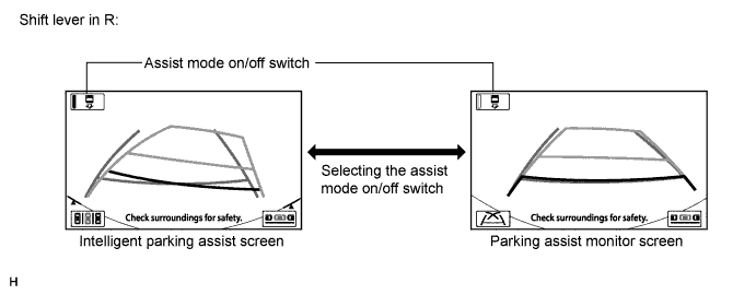
When the following conditions are met while the power switch is on (IG) or on (READY), the screen display can be switched by pressing the assist mode on/off switch.
Screen Displayed on Navigation Receiver Assembly Shift State Assist Mode On/Off Switch
(Indicator in switch)
Screen Displayed
(Display switches in the following sequence when assist mode on/off switch is pressed)
Navigation screen or information setting screen Changed from P to R ON
(Illuminated)
Navigation screen or information setting screen → Intelligent parking assist screen
(Intelligent parking assist mode)
OFF
(Not illuminated)
Navigation screen or information setting screen → Parking assist monitor screen
(Parking assist monitor mode)
-
-
DISPLAY MODE SETTING
-
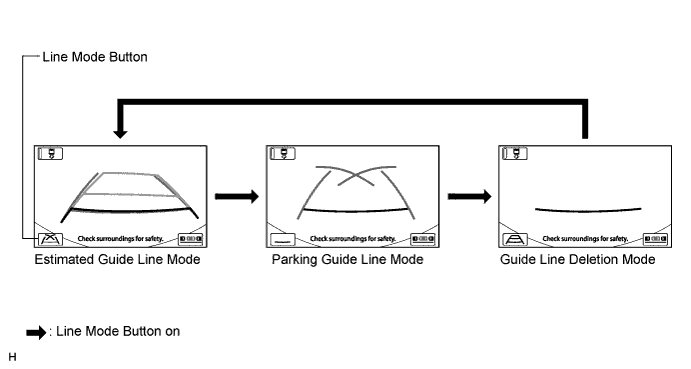
While the parking assist monitor screen is displayed, pressing the line mode button switches the parking assist monitor display mode.
Tech Tips
The display mode that has been selected at parking assist monitor screen applied at the intelligent parking assist screen.
Parking Assist Monitor Display Mode Parking Assist Monitor Display Mode Distance Guide Line
(Red with Black)
Vehicle Width Extension Line
(Green)
Predicted Path Line
(Yellow)
Parking Guide Line
(Green)
Estimated Guide Line Mode Displayed Displayed Displayed Not displayed Parking Guide Line Mode Displayed Displayed Not displayed Displayed Guide Line Deletion Mode Displayed Not displayed Not displayed Not displayed
-
-
PRE SUPPORT FUNCTION
-
Function Description
-
A pre support function is provided to assist the driver with initial positioning of the vehicle when backing-in mode or parallel parking mode operation is used.
-
-
Pre support Function Operation Condition
-
Before operating the function, assist mode should be turned on (the assist mode on/off switch indicator light should be on). This makes the intelligent parking assist screen appear on the navigation receiver assembly with the shift lever in R.
Tech Tips
When assist mode is off (when the assist mode on/off switch indicator light is off, the parking assist monitor screen is displayed on the navigation receiver assembly with the shift lever in R), the pre support function does not operate even when the parking assist pre support switch is pressed (the tone also does not sound).
-
For the pre support function, when the intelligent parking assist system is operating normally (no DTCs are stored) and the following conditions are met, pressing the parking assist pre support switch changes the image displayed on the screen and pre support operation starts.
Tech Tips
The display transition of the pre support function differs according to the market the vehicle is sold in.
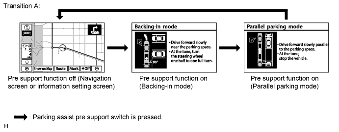
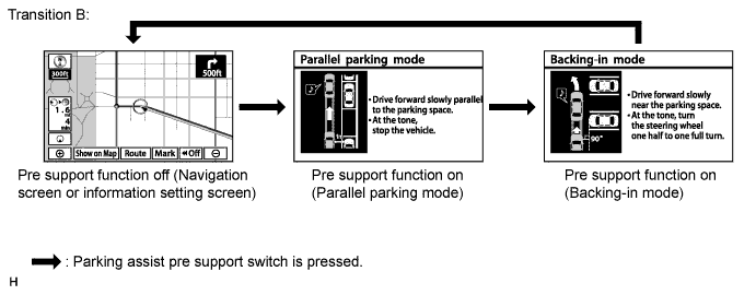
Transition Screen Displayed on Navigation Receiver Assembly Shift Position Vehicle Speed Screen Displayed
(Display switches in the following sequence when parking assist pre support switch is pressed)
A Navigation screen or information setting screen Other than P or R 15 km/h (9.3 mph) or less Pre support off (Navigation screen or information setting screen) → Pre support on (Backing-in mode) → Pre support on (Parallel parking mode) → Pre support off (Navigation screen or information setting screen)*1 B Navigation screen or information setting screen Other than P or R 15 km/h (9.3 mph) or less Pre support off (Navigation screen or information setting screen) → Pre support on (Parallel parking mode) → Pre support on (Backing-in mode) → Pre support off (Navigation screen or information setting screen)*1
-
*1: A tone sounds when the screen transfers.
-
-
-
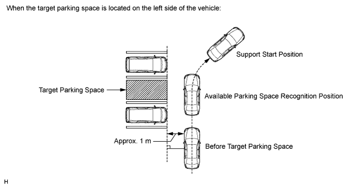
Backing-in Mode Operation
-
Press the parking assist pre support switch before the target parking space to turn on the pre support function (backing-in mode).
-
Drive the vehicle slowly while keeping a distance of approximately 1 m (3.3 ft.) from and perpendicular to the target parking space or vehicles around the target parking space. When the ultrasonic sensor (No. 1 ultrasonic sensor) detects an available parking space, start to turn the steering wheel from the straight ahead position when the tone sounds.
Tech Tips
-
An available parking space may not be detected by the ultrasonic sensor (No. 1 ultrasonic sensor) depending on the distance between the vehicle being parked and the target parking space or vehicles around the target parking space, vehicle orientation and vehicle speed.
-
A target parking space may not be detected by the ultrasonic sensor (No. 1 ultrasonic sensor) depending on the conditions around the target parking space. For details, refer to Precautions for the parking space detection sensor Click here.
-
When the ultrasonic sensor (No. 1 ultrasonic sensor) cannot detect a target parking space, a tone will not sound.
-
-
Drive the vehicle while turning the steering wheel and when the vehicle reaches the support start position (the tone will sound twice), stop the vehicle, return the steering wheel to the straight ahead position, and move the shift lever to R.
-
When the intelligent parking assist screen is displayed, the target parking frame will also displayed for the target parking space that is detected by the ultrasonic sensor (No. 1 ultrasonic sensor) during the pre support function operation.
-
-
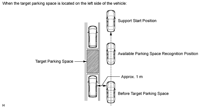
Parallel Parking Mode Operation
-
Press the parking assist pre support switch before the target parking space to turn on the pre support function (parallel parking mode).
-
Drive the vehicle slowly while keeping a distance of approximately 1 m (3.3 ft.) from and parallel to the target parking space or vehicles around the target parking space to allow the ultrasonic sensor (No. 1 ultrasonic sensor) to start detection.
Tech Tips
-
For parallel parking mode, a tone will not sound when the ultrasonic sensor (No. 1 ultrasonic sensor) detects the available parking space.
-
An available parking space may not be detected by the ultrasonic sensor (No. 1 ultrasonic sensor) depending on a distance between the vehicle being parked and the target parking space or vehicles around the target parking space, vehicle orientation and vehicle speed.
-
A target parking space may not be detected by the ultrasonic sensor (No. 1 ultrasonic sensor) depending on the conditions around the target parking space. For details, refer to Precautions for the parking space detection sensor Click here.
-
-
Drive as is and stop the vehicle when the vehicle reaches the support start position (the tone will sound twice), and move the shift lever to R.
Tech Tips
When the ultrasonic sensor (No. 1 ultrasonic sensor) cannot detect a target parking space, the tone will not sound.
-
When the intelligent parking assist screen is displayed, the target parking frame will also be displayed for the target parking space that is detected by the ultrasonic sensor (No. 1 ultrasonic sensor) during the pre support function operation.
-
-
-
COMMUNICATION SYSTEM OUTLINE
-
The components of the intelligent parking assist system communicate with each other through the AVC-LAN. The parking assist ECU judges the vehicle angle data transmitted via the AVC-LAN from the navigation receiver assembly (the data is calculated by the navigation receiver assembly by integrating the yaw rate of the gyro sensor built into the navigation receiver assembly).
-
If a short circuit or open circuit occurs in the AVC-LAN, communication is interrupted and this system will stop functioning.
-
-
DIAGNOSTIC FUNCTION OUTLINE
-
This intelligent parking assist system has a diagnostic function displayed in the navigation receiver assembly. This function enables the calibration (adjustment and verify) of the intelligent parking assist system Click here.
-
The intelligent parking assist system can check the following items by using the intelligent tester.
Item Proceed to DTC Data List / Active Test
-