BRAKE BOOSTER (for RHD) INSTALLATION

-
INSTALL BRAKE BOOSTER GASKET
-
Install a new brake booster gasket to the brake booster with master cylinder assembly.
-
-
INSTALL BRAKE BOOSTER WITH MASTER CYLINDER ASSEMBLY
-
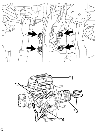
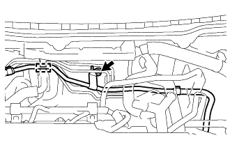
Text in Illustration *1 Connector Portion *2 Union *3 Push Rod Clevis and Boot *4 Front No. 2 Brake Tube Install the brake booster with master cylinder assembly with the 4 nuts.
- Torque:
- 13 N*m { 130 kgf*cm, 9 ft.*lbf }
Note
-
Do not kink or damage the brake lines.
-
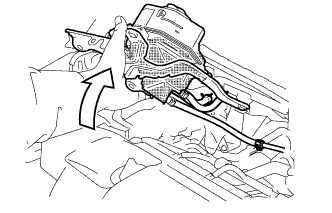
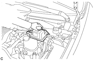
Do not carry the brake booster with master cylinder assembly by the portion shown in the illustration.
-
Be careful not to allow brake fluid to enter the connector of ECU.
-
If installing a new brake booster with master cylinder assembly, do not remove the hole plugs before connecting the brake lines because the brake booster with master cylinder is filled with brake fluid.
-
Engage the grommet of the brake line.
-
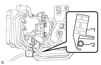
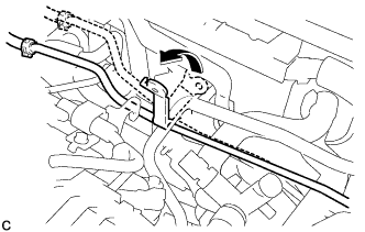
Text in Illustration *1 Clamp *2 Brake Line Set the brake line to the clamp as shown in the illustration.
Note
Securely install the brake line so that it contacts the clamp as shown in the illustration.
-
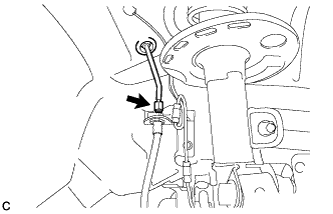
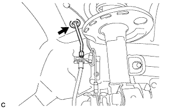
Using a union nut wrench, connect the brake line to the front flexible hose RH.
- Torque:
- 15 N*m { 155 kgf*cm, 11 ft.*lbf }
Note
-
Do not kink or damage the brake lines.
-
Use the formula to calculate special torque values for situations where the union nut wrench is combined with a torque wrench Click here.
-
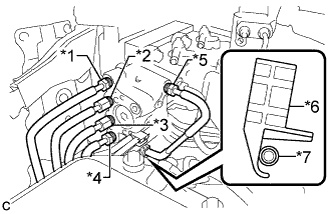
Text in Illustration *1 to Front Wheel Cylinder LH *2 to Rear Wheel Cylinder RH *3 to Brake Booster Pump Assembly *4 to Rear Wheel Cylinder LH *5 to Front Wheel Cylinder RH *6 Clamp *7 Brake Line Using a union nut wrench, connect each brake line to the brake booster with master cylinder assembly as shown in the illustration.
- Torque:
- 15 N*m { 155 kgf*cm, 11 ft.*lbf }
Note
-
Do not kink or damage the brake lines.
-
Securely install the brake line so that it contacts the clamp as shown in the illustration.
-
Use the formula to calculate special torque values for situations where the union nut wrench is combined with a torque wrench Click here.
-
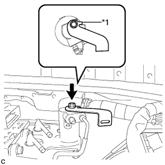
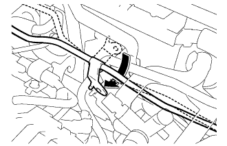
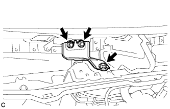
Text in Illustration *1 Stopper Install the wire harness clamp bracket to the brake booster with master cylinder assembly with the bolt.
- Torque:
- 13 N*m { 133 kgf*cm, 10 ft.*lbf }
Note
Securely install the wire harness clamp bracket so that its stopper contacts the brake booster with master cylinder assembly as shown in the illustration.
-
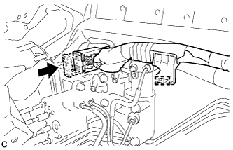
Connect the connector.
Note
-
Make sure that the connector can be connected smoothly. Do not allow water, oil or dirt to enter.
-
Make sure that the connector lock is locked securely.
-
-
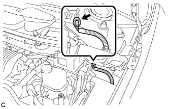
Engage the clamp.
-
-
CONNECT NO. 1 RESERVOIR HOSE
-
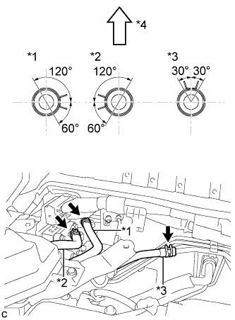
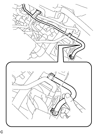
Text in Illustration *1 No. 1 Reservoir Hose *2 No. 2 Reservoir Hose *3 No. 2 Brake Actuator Hose *4 Top of Vehicle Connect the No. 1 reservoir hose, No. 2 reservoir hose and No. 2 brake actuator hose with the clips.
Note
-
Make sure to match the identification marks on the hoses, brake booster with master cylinder assembly and brake actuator tube.
Identification Mark Color Connection Color No. 1 Reservoir Hose White White (Unpainted) No. 2 Reservoir Hose Green Green No. 2 Brake Actuator Hose Yellow Yellow -
When connecting the reservoir hose, face the identification mark to the top of the vehicle.
-
Make sure to install the hose to the proper location.
-
Install the clip within the range as shown in the illustration.
-
-
-
CONNECT NO. 2 RESERVOIR HOSE
-
CONNECT NO. 2 BRAKE ACTUATOR HOSE
-
BLEED BRAKE ACTUATOR TUBE
Note
Make sure to bleed the air from the No. 1 brake actuator tube. If the air remains in the No. 1 brake actuator tube, the air enters into the brake booster pump assembly and it may cause the brake booster pump assembly to be damaged.
-
Remove the brake master cylinder reservoir filler cap assembly.
-
Add brake fluid into the reservoir between the MAX and MIN level on the brake fluid reservoir.
Brake Fluid SAE J1703 or FMVSS No. 116 DOT3 -
Install the brake master cylinder reservoir filler cap assembly.
-
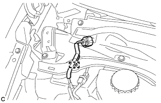
Remove the nut, disengage the clamp and separate the No. 1 brake actuator tube from the vehicle body.
-
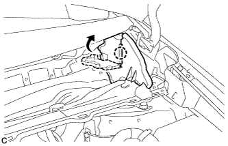
Lift up the brake master cylinder reservoir with bracket as far as possible.
Note
Do not spill the brake fluid.
-
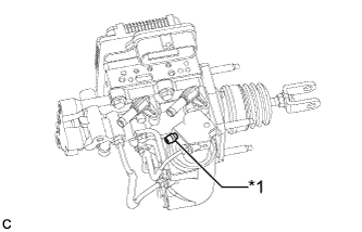
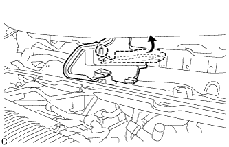
While holding the brake master cylinder reservoir with bracket, twist and hold the No. 1 brake actuator tube 90° toward the vehicle front, and wait at 5 seconds.*1
Note
Do not damage the hoses.
Tech Tips
Keeping the No. 1 brake actuator tube twisted causes the remaining air inside the No. 1 brake actuator tube to be expelled to the brake master cylinder reservoir assembly.
-
Return the No. 1 brake actuator tube to its original state.
-
While holding the brake master cylinder reservoir with bracket, twist and hold the No. 1 brake actuator tube 90° toward the vehicle rear, and wait at 5 seconds.
Note
Do not damage the hoses.
Tech Tips
Keeping the No. 1 brake actuator tube twisted causes the remaining air inside the No. 1 brake actuator tube to be expelled to the brake master cylinder reservoir assembly.
-
Return the No. 1 brake actuator tube to its original state.*2
-
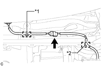
Repeat steps *1 to *2, 5 times.
-
While holding the brake master cylinder reservoir with bracket, pinch the brake actuator hose 10 times with your fingers.
Note
Do not use pliers or similar to pinch the brake actuator hose. Doing so may cause damage to the brake actuator hose. Make sure to use your fingers.
-
Repeat steps *1 to *2, 5 times again, and check that air is not expelled from the No. 1 brake actuator tube.
-
Engage the clamp and install the No. 1 brake actuator tube with the nut.
- Torque:
- 8.4 N*m { 85 kgf*cm, 74 in.*lbf }
-
-
INSTALL BRAKE MASTER CYLINDER RESERVOIR WITH BRACKET
-
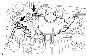
Install the brake master cylinder reservoir with bracket with the 2 nuts.
- Torque:
- 50 N*m { 510 kgf*cm, 37 ft.*lbf }
-
Engage the clamp.
-
-
INSTALL PUSH ROD PIN
-
Apply lithium soap base glycol grease to the push rod pin and installation hole of the brake pedal support assembly.
-
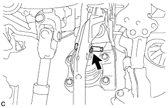
Install the push rod pin and a new clip to connect the push rod clevis to the brake pedal support assembly.
-
-
INSTALL BRAKE PEDAL RETURN SPRING
-
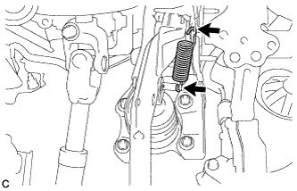
Install the brake pedal return spring to the brake pedal support assembly and push rod pin.
-
-
FILL RESERVOIR WITH BRAKE FLUID
-
CONNECT CABLE TO NEGATIVE BATTERY TERMINAL
Note
When disconnecting the cable, some systems need to be initialized after the cable is reconnected Click here.
-
BLEED BRAKE SYSTEM
-
Remove the outer cowl top panel sub-assembly.
-
Bleed the brake system.
-
Wait at least 2 minutes with the power switch off, and disconnect the reservoir level switch connector.
Note
Do not depress the brake pedal or open/close the doors until the reservoir level switch connector is disconnected.
Tech Tips
This procedure is not required if the reservoir level switch connector has been disconnected.
-
Remove the brake master cylinder reservoir filler cap assembly.
-
Add brake fluid into the reservoir between MAX and MIN level on the brake fluid reservoir.
Brake fluid SAE J1703 or FMVSS No. 116 DOT3 -
Connect the intelligent tester to the DLC3 and turn the power switch on (IG).
-
Turn the intelligent tester on and enter the following menus: Chassis / ABS/VSC/TRC / Air Bleeding.
-
Select the "ABS actuator has been replaced" on the intelligent tester display, and bleed air from the brake fluid following the instructions on the intelligent tester.
Note
Before following the instructions on the intelligent tester to perform linear valve offset calibration, release the parking brake. When calibration is complete, immediately apply the parking brake.
-
Text in Illustration *1 Stroke Simulator Bleeder Plug After air bleeding, tighten each bleeder plug.
- Torque:
- front bleeder plug
- 8.3 N*m { 85 kgf*cm, 73 in.*lbf }
- rear bleeder plug
- 11 N*m { 112 kgf*cm, 8 ft.*lbf }
- stroke simulator bleeder plug
- 8.5 N*m { 87 kgf*cm, 75 in.*lbf }
Tech Tips
The stroke simulator bleeder plug is positioned as shown in the illustration.
-
Clear the DTCs Click here.
-
Turn the intelligent tester off and turn the power switch off.
-
-
Install the brake master cylinder reservoir filler cap.
-
Inspect for brake fluid leaks.
-
Install the outer cowl top panel sub-assembly.
-
-
INSPECT AND ADJUST BRAKE PEDAL
-
PERFORM EMERGENCY BRAKE SIGNAL LEARNING (w/ Emergency Brake Signal)
Tech Tips
After the brake booster with master cylinder assembly is replaced, perform emergency brake signal leaning Click here.
-
OBTAIN ZERO POINT OF YAW RATE AND ACCELERATION SENSOR
Tech Tips
After the brake booster with master cylinder assembly is replaced, obtain the zero point of the yaw rate and acceleration sensor Click here.
-
INSTALL OUTER COWL TOP PANEL SUB-ASSEMBLY
-
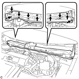
Install the outer cowl top panel with the 9 bolts.
- Torque:
- 12 N*m { 122 kgf*cm, 9 ft.*lbf }
-
Bend the water guard plate RH and engage the claw.
-
Bend the No. 1 heater air duct splash shield seal and engage the claw.
-
Engage the clamp*2 of the wire harness.
-
Engage the clamp*1 and connect the connector (w/ Windshield Deicer).
-
Engage the clamp of the wire harness.
-
-
INSTALL COWL BODY MOUNTING REINFORCEMENT LH
-
Install the cowl body mounting reinforcement LH with the 3 bolts.
- Torque:
- 12 N*m { 122 kgf*cm, 9 ft.*lbf }
-
-
INSTALL WINDSHIELD WIPER MOTOR AND LINK ASSEMBLY
-
INSTALL NO. 1 INSTRUMENT PANEL UNDER COVER SUB-ASSEMBLY
-
Connect each connector.
-
Engage the guide and 2 claws.
-
Install the No. 1 instrument panel under cover sub-assembly with the screw <D>.
-
-
INSTALL REAR NO. 3 FLOOR BOARD
-

Engage the 2 guides to install the rear No. 3 floor board.
-
-
INSTALL REAR DECK FLOOR BOX
-
Install the rear deck floor box.
-
-
INSTALL REAR NO. 2 FLOOR BOARD
-

Engage the 3 guides <A>.
-
Engage the 2 guides <B> and install the rear No. 2 floor board as shown in the illustration.
-