BRAKE PEDAL (for RHD) REMOVAL

-
REMOVE UPPER INSTRUMENT PANEL ASSEMBLY
Tech Tips
Refer to the instructions for Removal of the upper instrument panel assembly Click here.
-
REMOVE NO. 1 INSTRUMENT PANEL UNDER COVER SUB-ASSEMBLY
-
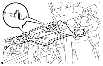
Remove the screw <D>.
-
Disengage the 2 claws and guide.
-
Disconnect each connector and remove the No. 1 instrument panel under cover sub-assembly.
-
-
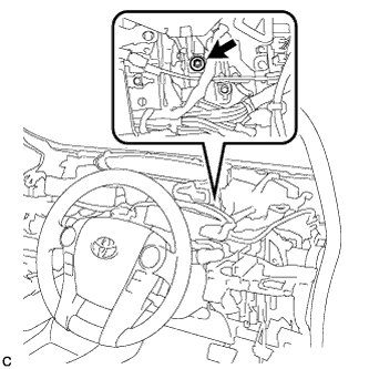
REMOVE ECU INTEGRATION BOX RH
-
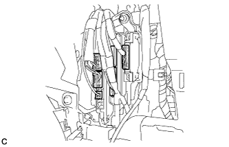
Disconnect the connectors.
-
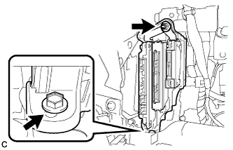
Remove the nut, bolt and ECU integration box RH.
-
-
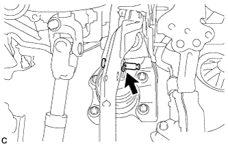
REMOVE BRAKE PEDAL STROKE SENSOR ASSEMBLY
-
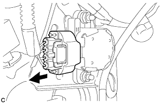
Disconnect the sensor connector.
-
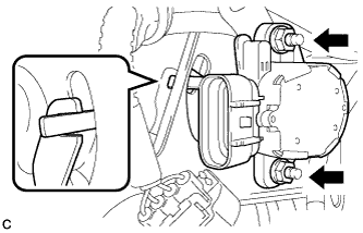
Remove the 2 nuts and brake pedal stroke sensor assembly.
Note
Do not drop the brake pedal stroke sensor assembly. If the brake pedal stroke sensor assembly has been dropped, replace the brake pedal stroke sensor assembly with a new one.
-
-
REMOVE STOP LIGHT SWITCH ASSEMBLY
-
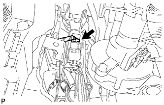
Disconnect the connector.
-
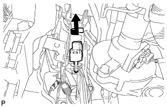
Turn the stop light switch assembly counterclockwise and remove it.
-
-
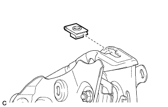
REMOVE STOP LIGHT SWITCH MOUNTING ADJUSTER
-
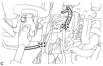
REMOVE BRAKE PEDAL RETURN SPRING
-
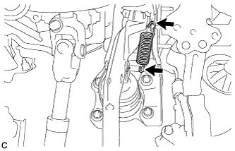
Remove the brake pedal return spring from the brake pedal support sub-assembly and push rod pin.
-
-
REMOVE PUSH ROD PIN
-
Remove the clip and push rod pin to separate the brake pedal sub-assembly from the push rod clevis.
-
-
REMOVE BRAKE PEDAL SUPPORT ASSEMBLY
-
Remove the bolt and separate the brake pedal support assembly from the instrument panel reinforcement.
-
Disengage the 2 clamps.
-
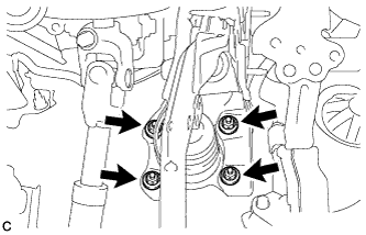
Remove the 4 nuts and brake pedal support assembly.
-
Remove the nut from the brake pedal support assembly.
-