BRAKE PEDAL (for LHD) REMOVAL

-
REMOVE UPPER INSTRUMENT PANEL ASSEMBLY
-
REMOVE NO. 1 INSTRUMENT PANEL UNDER COVER SUB-ASSEMBLY
-
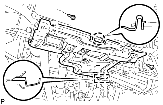
Remove the 2 screws <D>.
-
Disengage the claw and guide.
-
Disconnect each connector and remove the No. 1 instrument panel under cover sub-assembly.
-
-
REMOVE STOP LIGHT SWITCH ASSEMBLY
-
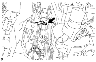
Disconnect the connector.
-
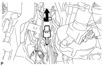
Turn the stop light switch assembly counterclockwise and remove it.
-
-
REMOVE STOP LIGHT SWITCH MOUNTING ADJUSTER
-
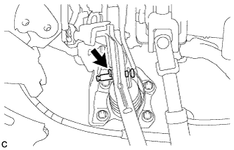
REMOVE BRAKE PEDAL RETURN SPRING
-
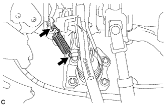
Remove the brake pedal return spring from the brake pedal support assembly and push rod pin.
-
-
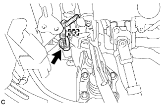
REMOVE PUSH ROD PIN
-
Remove the clip and push rod pin to separate the brake pedal support assembly from the push rod clevis.
-
-
SEPARATE INSTRUMENT PANEL JUNCTION BLOCK ASSEMBLY
-
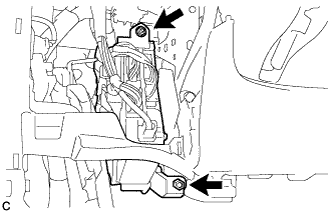
Remove the bolt and nut, and separate the instrument panel junction block assembly.
-
-
REMOVE BRAKE PEDAL SUPPORT ASSEMBLY
-
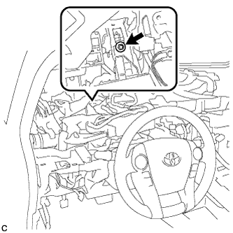
Remove the bolt and separate the brake pedal support assembly from the instrument panel reinforcement.
-
Disengage the clamp and disconnect the connector from the brake pedal stroke sensor assembly.
-
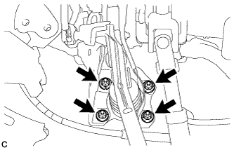
Remove the 4 nuts and brake pedal support assembly.
-
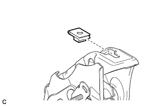
Remove the nut from the brake pedal support assembly.
-