BRAKE BOOSTER PUMP REMOVAL

-
PRECAUTION (w/ Navigation System for HDD)
Note
After the power switch is turned off, the display and navigation module display (HDD navigation system) records various types of memory and settings. As a result, after turning the power switch off, make sure to wait at least 60 seconds before disconnecting the cable from the negative (-) battery terminal.
-
REMOVE REAR NO. 2 FLOOR BOARD (for RHD)
-

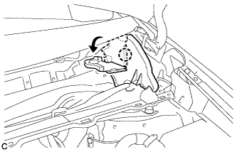
Disengage the 2 guides <A> as shown in the illustration.
-
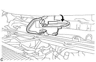
Disengage the 3 guides <B> and remove the rear No. 2 floor board.
-
-
REMOVE REAR DECK FLOOR BOX (for RHD)
-
Remove the rear deck floor box.
-
-
REMOVE REAR NO. 3 FLOOR BOARD (for RHD)
-

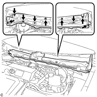
Disengage the 2 guides and remove the rear No. 3 floor board.
-
-
DISABLE BRAKE CONTROL (for RHD)
-
Wait at least 2 minutes after the power switch off.
Note
When the brake pedal is depressed or the door courtesy switch is turned on even if the power switch is off, the brake control system activates. Therefore do not depress the brake pedal or open/close the doors until the reservoir level switch connector is disconnected.
-
Disconnect the reservoir level switch connector with the parking brake applied.
-
Disconnect the cable from the negative (-) battery terminal.
Note
When disconnecting the cable, some systems need to be initialized after the cable is reconnected Click here.
-
Depress the brake pedal 40 times or more to return all the fluid in the accumulator back to the reservoir.
-
Check that the brake pedal can not be further depressed.
-
Release the parking brake.
-
-
REMOVE WINDSHIELD WIPER MOTOR AND LINK ASSEMBLY (for RHD)
Tech Tips
Refer to the procedure up to Remove windshield wiper and motor link assembly Click here.
-
REMOVE COWL BODY MOUNTING REINFORCEMENT LH (for RHD)
-
Remove the 3 bolts and cowl body mounting reinforcement LH.
-
-
REMOVE OUTER COWL TOP PANEL SUB-ASSEMBLY (for RHD)
-
Disengage the clamp and separate the wire harness from the outer cowl top panel sub-assembly.
-
Disengage the clamp*1 and disconnect the connector (w/ Windshield Deicer).
-
Disengage the clamp*2 and separate the wire harness from the outer cowl top panel sub-assembly.
-
Disengage the claw and bend the No. 1 heater air duct splash shield seal.
-
Disengage the claw and bend the water guard plate RH.
-
Remove the 9 bolts and outer cowl top panel sub-assembly.
-
-
DRAIN BRAKE FLUID (for RHD)
Note
If brake fluid leaks onto any painted surface, immediately wash it off.
-
REMOVE BRAKE BOOSTER WITH MASTER CYLINDER ASSEMBLY (for LHD)
Tech Tips
Refer to the procedure up to Remove Brake Booster with Master Cylinder Assembly Click here.
-
REMOVE FRONT CROSS MEMBER SUB-ASSEMBLY
Tech Tips
Refer to the procedure up to Remove Front Cross Member Sub-assembly Click here.
-
REMOVE NO. 5 BRAKE ACTUATOR BRACKET
-
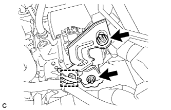
Remove the 2 nuts and No. 5 brake actuator bracket.
-
Separate the wire harness clamp.
-
-
REMOVE BRAKE BOOSTER PUMP ASSEMBLY WITH BRACKET
-
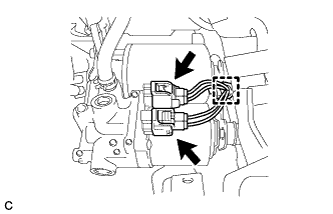
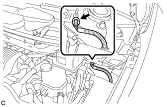
Disconnect the 2 connectors and separate the clamp from the brake booster pump assembly.
-
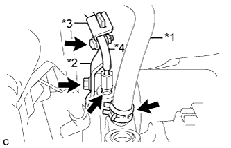
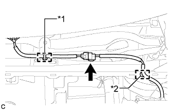
Text in Illustration *1 Brake Actuator Hose *2 No. 2 Brake Tube Clamp *3 No. 1 Brake Tube Clamp *4 Front No. 1 Brake Tube Remove the clip and brake actuator hose.
-
Remove the 2 bolts, No. 1 brake tube clamp and No. 2 brake tube clamp.
-
Disconnect the front No. 1 brake tube.
-
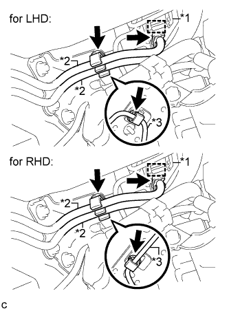
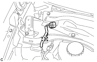
Text in Illustration *1 Wire Harness Clamp *2 Fuel Line *3 Front No. 4 Brake Tube Separate the wire harness clamp, 2 fuel lines and front No. 4 brake tube from the brake booster pump assembly.
-
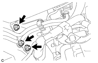
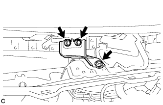
Remove the 3 nuts and brake booster pump assembly with bracket.
-
-
REMOVE BRAKE BOOSTER PUMP ASSEMBLY
-
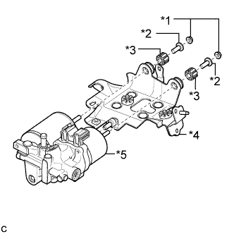
Text in Illustration *1 Nut *2 Brake Actuator Case Collar *3 Brake Booster Pump Bushing *4 Brake Actuator Bracket Assembly *5 Brake Booster Pump Assembly Remove the 2 nuts, brake booster pump bushings, brake actuator case collars and brake booster pump assembly from the brake actuator bracket assembly.
-