SKID CONTROL BUZZER (for RHD) REMOVAL

Note
While the battery is connected, even if the power switch is off, the brake control system activates when the brake pedal is depressed or any door courtesy switch turns on. Therefore, when servicing the brake system components, do not operate the brake pedal or open/close the doors while the battery is connected.
-
PRECAUTION (w/ Navigation System for HDD)
Note
After the power switch is turned off, the display and navigation module display (HDD navigation system) records various types of memory and settings. As a result, after turning the power switch off, make sure to wait at least 60 seconds before disconnecting the cable from the negative (-) battery terminal.
-
REMOVE REAR NO. 2 FLOOR BOARD
-

Disengage the 2 guides <A> as shown in the illustration.
-
Disengage the 3 guides <B> and remove the rear No. 2 floor board.
-
-
REMOVE REAR DECK FLOOR BOX
-
Remove the rear deck floor box.
-
-
REMOVE REAR NO. 3 FLOOR BOARD
-

Disengage the 2 guides and remove the rear No. 3 floor board.
-
-
DISCONNECT CABLE FROM NEGATIVE BATTERY TERMINAL
Note
When disconnecting the cable, some systems need to be initialized after the cable is reconnected Click here.
-
REMOVE FRONT DOOR SCUFF PLATE RH
Tech Tips
Perform the same procedure as for the LHD Click here.
-
REMOVE COWL SIDE TRIM SUB-ASSEMBLY RH
Tech Tips
Perform the same procedure as for the LHD Click here.
-
REMOVE LOWER INSTRUMENT PANEL FINISH PANEL
Tech Tips
Perform the same procedure as for the LHD Click here.
-
REMOVE ECU INTEGRATION BOX RH
-
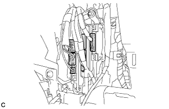
Disconnect the connectors.
-
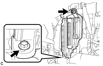
Remove the nut, bolt and ECU integration box RH.
-
-
REMOVE SKID CONTROL BUZZER ASSEMBLY
-
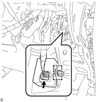
Remove the skid control buzzer assembly.
-
Disconnect the skid control buzzer connector.
-