FRONT SPEED SENSOR REMOVAL

Note
While the battery is connected, even if the power switch is off, the brake control system activates when the brake pedal is depressed or any door courtesy switch turns on. Therefore, when servicing the brake system components, do not operate the brake pedal or open/close the doors while the battery is connected.
Tech Tips
-
Use the same procedure for the LH side and RH side.
-
The following procedure is for the LH side.
-
If the sensor rotor needs to be replaced, replace it together with the front axle hub and bearing assembly.
-
PRECAUTION (w/ Navigation System for HDD)
Note
After the power switch is turned off, the display and navigation module display (HDD navigation system) records various types of memory and settings. As a result, after turning the power switch off, make sure to wait at least 60 seconds before disconnecting the cable from the negative (-) battery terminal.
-
REMOVE REAR NO. 2 FLOOR BOARD
-

Disengage the 2 guides <A> as shown in the illustration.
-
Disengage the 3 guides <B> and remove the rear No. 2 floor board.
-
-
REMOVE REAR DECK FLOOR BOX
-
Remove the rear deck floor box.
-
-
REMOVE REAR NO. 3 FLOOR BOARD
-

Disengage the 2 guides and remove the rear No. 3 floor board.
-
-
DISCONNECT CABLE FROM NEGATIVE BATTERY TERMINAL
Note
When disconnecting the cable, some systems need to be initialized after the cable is reconnected Click here.
-
REMOVE FRONT WHEEL
-
REMOVE FRONT FENDER LINER
-
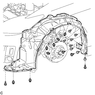
Remove the 12 clips, 4 screws, 3 grommets, and front fender liner.
Tech Tips
Use the same procedure for the RH side and LH side.
-
-
REMOVE FRONT SPEED SENSOR
-
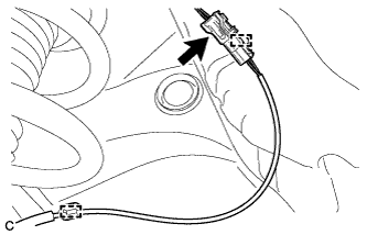
Remove the 2 clamps and disconnect the front speed sensor connector.
-
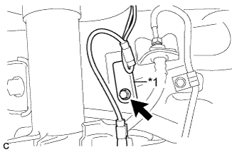
Text in Illustration *1 No. 2 Sensor Clamp Remove the bolt and No. 2 sensor clamp from the body.
-
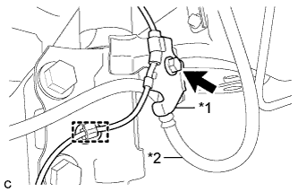
Text in Illustration *1 No. 1 Sensor Clamp *2 Front Brake Flexible Hose Remove the bolt, No. 1 sensor clamp and front brake flexible hose together from the shock absorber assembly.
-
Remove the clamp from the shock absorber.
-
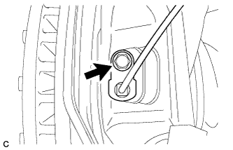
Remove the bolt and front speed sensor.
Note
-
Prevent foreign matter from attaching to the front speed sensor tip.
-
Clean the speed sensor installation hole and the contact surfaces every time the front speed sensor is removed.
-
-