ELECTRONICALLY CONTROLLED BRAKE SYSTEM Skid Control Buzzer Circuit
DESCRIPTION
The skid control buzzer sounds intermittently to warn the driver when the accumulator pressure is abnormally low. This buzzer also sounds intermittently when VSC is operating.
Tech Tips
The skid control buzzer may sound when the accumulator pressure drops due to frequent braking Click here.
WIRING DIAGRAM
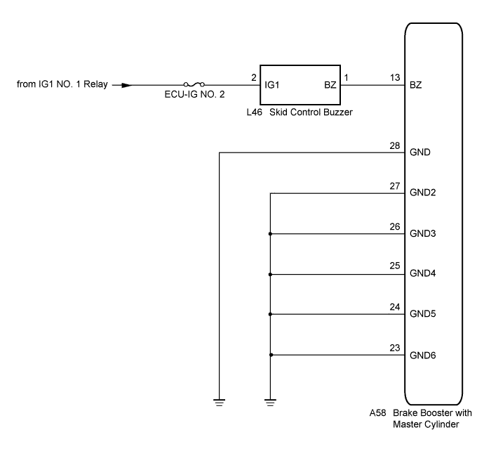
INSPECTION PROCEDURE
Note
When replacing the brake booster with master cylinder (skid control ECU), perform initialization, calibration of the linear solenoid valve and emergency brake signal learning Click here.
PROCEDURE
-
CHECK BUZZER OPERATION
-
Confirm problem symptoms of the skid control buzzer according to the customer problem analysis.
Tech Tips
If the buzzer stops after sounding continuously, a temporary drop in accumulator pressure is the suspected cause.
Result Result Proceed to Buzzer does not sound A Buzzer sounds constantly B
B 
INSPECT SKID CONTROL ECU Click here
A 
-
-
PERFORM ACTIVE TEST USING INTELLIGENT TESTER (SKID CONTROL BUZZER)
-
Connect the intelligent tester to the DLC3.
-
Turn the power switch on (IG).
-
Select the Active Test on the intelligent tester Click here.
ABS/VSC/TRC Tester Display Test Part Control Range Diagnostic Note Buzzer Skid control buzzer Buzzer ON/OFF Buzzer can be heard -
Check that the buzzer sounds/stops when turning the skid control buzzer on/off using the intelligent tester.
Result Result Proceed to Buzzer does not sound A Buzzer sounds/stops B Tech Tips
If troubleshooting has been carried out according to Problem Symptoms Table, refer back to the table and proceed to the next step Click here.
B 
CHECK FOR INTERMITTENT PROBLEMS Click here
A
-
-
INSPECT SKID CONTROL BUZZER (POWER SOURCE TERMINAL)
-
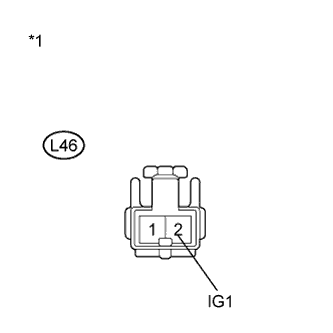
Text in Illustration *1 Front view of wire harness connector
(to Skid Control Buzzer)
Turn the power switch off.
-
Disconnect the skid control buzzer connector.
-
Turn the power switch on (IG).
-
Measure the voltage according to the value(s) in the table below.
Standard Voltage Tester Connection Switch Condition Specified Condition L46-2 (IG1) - Body ground Power switch on (IG) 11 to 14 V
NG
REPAIR OR REPLACE HARNESS OR CONNECTOR (POWER SOURCE CIRCUIT)
OK
-
-
INSPECT SKID CONTROL BUZZER
-
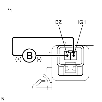
Text in Illustration *1 Component without harness connected
(Skid Control Buzzer)
Turn the power switch off.
-
Connect a negative (-) lead from the battery to terminal 1, and a positive (+) lead to terminal 2 of the skid control buzzer, and then check that the buzzer sounds.
OK The skid control buzzer sounds. Result Result Proceed to OK A NG (for LHD) B NG (for RHD) C
B
REPLACE SKID CONTROL BUZZER Click here
C
REPLACE SKID CONTROL BUZZER Click here
A
-
-
CHECK HARNESS AND CONNECTOR (SKID CONTROL ECU - SKID CONTROL BUZZER)
-
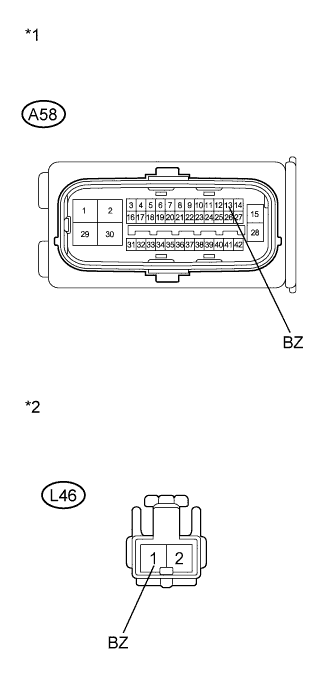
Text in Illustration *1 Front view of wire harness connector
(to Skid Control ECU)
*2 Front view of wire harness connector
(to Skid Control Buzzer)
Disconnect the skid control ECU connector 2 minutes after the power switch is turned off.
Tech Tips
Do not open/close the driver door within 2 minutes after the power switch is turned off.
-
Measure the resistance according to the value(s) in the table below.
Standard Resistance Tester Connection Condition Specified Condition A58-13 (BZ) - L46-1 (BZ) Always Below 1 Ω A58-13 (BZ) - Body ground Always 10 kΩ or higher
NG
REPAIR OR REPLACE HARNESS OR CONNECTOR
OK
-
-
INSPECT SKID CONTROL ECU (GND TERMINAL)
-
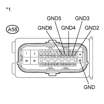
Text in Illustration *1 Front view of wire harness connector
(to Skid Control ECU)
Measure the resistance according to the value(s) in the table below.
Standard Resistance Tester Connection Condition Specified Condition A58-28 (GND) - Body ground Always Below 1 Ω A58-27 (GND2) - Body ground Always Below 1 Ω A58-26 (GND3) - Body ground Always Below 1 Ω A58-25 (GND4) - Body ground Always Below 1 Ω A58-24 (GND5) - Body ground Always Below 1 Ω A58-23 (GND6) - Body ground Always Below 1 Ω Result Result Proceed to OK (for LHD) A OK (for RHD) B NG C Tech Tips
If troubleshooting has been carried out according to Problem Symptoms Table, refer back to the table and proceed to the next step before replacing the part Click here.
B
REPLACE BRAKE BOOSTER WITH MASTER CYLINDER Click here
C
REPAIR OR REPLACE HARNESS OR CONNECTOR (GND CIRCUIT)
A 
REPLACE BRAKE BOOSTER WITH MASTER CYLINDER Click here
-
-
INSPECT SKID CONTROL ECU
-
Disconnect the skid control ECU connector.
-
Check that the skid control buzzer operation.
Result Result Proceed to Buzzer stops (for LHD) A Buzzer stops (for RHD) B Buzzer sounds constantly C Tech Tips
If troubleshooting has been carried out according to Problem Symptoms Table, refer back to the table and proceed to the next step before replacing the part Click here.
B
REPLACE BRAKE BOOSTER WITH MASTER CYLINDER Click here
C
REPLACE SKID CONTROL BUZZER Click here
A
REPLACE BRAKE BOOSTER WITH MASTER CYLINDER Click here
-
-
REPLACE SKID CONTROL BUZZER
-
Reconnect the skid control ECU connector.
-
Replace the skid control buzzer Click here for LHD or Click here for RHD).
-
Check that the skid control buzzer operation.
Result Result Proceed to Buzzer stops A Buzzer sounds constantly B Tech Tips
If troubleshooting has been carried out according to Problem Symptoms Table, refer back to the table and proceed to the next step before replacing the part Click here.
B
CHECK IF CONNECTOR IS SECURELY CONNECTED Click here
A
END
-
-
CHECK IF CONNECTOR IS SECURELY CONNECTED
-
Gently jiggle the connectors and wire harnesses and check the skid control buzzer operation.
Result Result Proceed to Buzzer stops A Buzzer sounds constantly B Tech Tips
If troubleshooting has been carried out according to Problem Symptoms Table, refer back to the table and proceed to the next step before replacing the part Click here.
B
REPAIR OR REPLACE HARNESS OR CONNECTOR
A
END
-