REAR SPEED SENSOR REMOVAL

Note
-
When the brake pedal is first depressed after replacing the brake pads or pushing back the disc brake piston, DTC C1214 may be output. As there is no malfunction, clear the DTC.
-
While the battery is connected, even if the power switch is off, the brake control system activates when the brake pedal is depressed or any door courtesy switch turns on. Therefore, when servicing the brake system components, do not operate the brake pedal or open/close the doors while the battery is connected.
Tech Tips
-
Use the same procedure for the RH side and LH side.
-
The procedure listed below is for the LH side.
-
If the sensor rotor needs to be replaced, replace it together with the rear axle hub and bearing assembly.
-
The rear speed sensor is a component of the rear axle hub and bearing assembly. If the sensor malfunctions, replace the rear axle hub and bearing assembly.
-
PRECAUTION (w/ Navigation System for HDD)
Note
After the power switch is turned off, the display and navigation module display (HDD navigation system) records various types of memory and settings. As a result, after turning the power switch off, make sure to wait at least 60 seconds before disconnecting the cable from the negative (-) battery terminal.
-
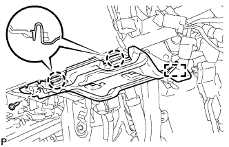
REMOVE REAR NO. 2 FLOOR BOARD
-

Disengage the 2 guides <A> as shown in the illustration.
-
Disengage the 3 guides <B> and remove the rear No. 2 floor board.
-
-
REMOVE REAR DECK FLOOR BOX
-
Remove the rear deck floor box.
-
-
REMOVE REAR NO. 3 FLOOR BOARD
-

Disengage the 2 guides and remove the rear No. 3 floor board.
-
-
DISABLE BRAKE CONTROL
-
Wait at least 2 minutes after the power switch off.
Note
When the brake pedal is depressed or the door courtesy switch is turned on even if the power switch is off, the brake control system activates. Therefore do not depress the brake pedal or open/close the doors until the reservoir level switch connector is disconnected.
-
Disconnect the reservoir level switch connector with the parking brake applied.
-
Disconnect the cable from the negative (-) battery terminal.
Note
When disconnecting the cable, some systems need to be initialized after the cable is reconnected Click here.
-
Depress the brake pedal 40 times or more to return all the fluid in the accumulator back to the reservoir.
-
Check that the brake pedal can not be further depressed.
-
Release the parking brake.
-
-
REMOVE REAR WHEEL
-
REMOVE FRONT DOOR SCUFF PLATE LH (for LHD)
-
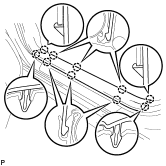
Disengage the 10 claws and remove the front door scuff plate LH.
-
-
REMOVE COWL SIDE TRIM SUB-ASSEMBLY LH (for LHD)
-
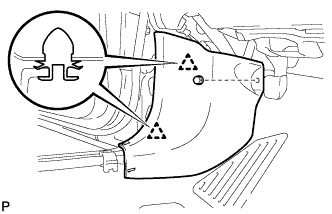
Remove the clip.
-
Disengage the 2 clips and remove the cowl side trim sub-assembly LH.
-
-
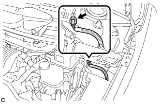
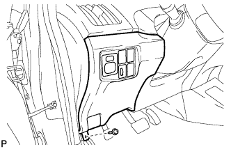
REMOVE LOWER INSTRUMENT PANEL FINISH PANEL ASSEMBLY (for LHD)
-
Remove the screw <C>.
-
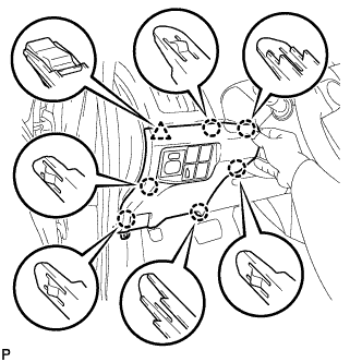
Disengage the 6 claws and clip as shown in the illustration.
-
Disengage the claw and 2 guides and disconnect the hood lock control cable.
-
Disconnect each connector and clamp, and remove the lower instrument panel finish panel assembly.
-
-
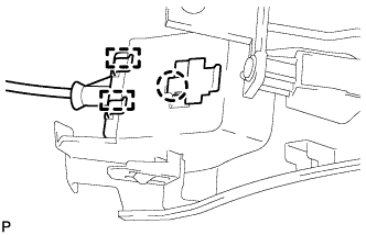
REMOVE NO. 1 INSTRUMENT PANEL UNDER COVER SUB-ASSEMBLY (for RHD)
-
Remove the screw <D>.
-
Disengage the 2 claws and guide.
-
Disconnect each connector and remove the No. 1 instrument panel under cover sub-assembly.
-
-
LOOSEN PARKING BRAKE CABLE
-
Completely release the parking brake pedal.
-
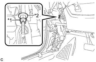
Text in Illustration *1 Lock Nut *2 Adjusting Nut Loosen the lock nut and adjusting nut to completely release the parking brake cable.
-
-
DISCONNECT REAR SPEED SENSOR WIRE
-
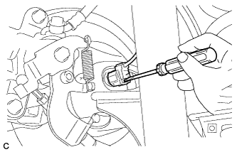
Using a screwdriver, disconnect the connector from the rear speed sensor.
Note
Be careful not to damage the rear speed sensor.
-
-
DISCONNECT NO. 3 PARKING BRAKE CABLE ASSEMBLY
-
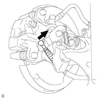
Separate the No. 3 parking brake cable assembly from the rear disc brake cylinder assembly.
-
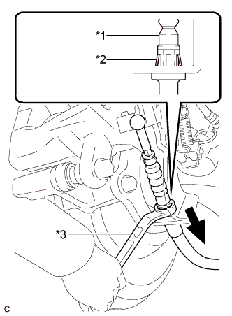
Text in Illustration *1 No. 3 Parking Brake Cable Assembly *2 Clip *3 Offset Wrench (14 mm) Separate the No. 3 parking brake cable assembly from the rear disc brake cylinder assembly.
Tech Tips
Insert an offset wrench (14 mm) at the base of the No. 3 parking brake cable assembly as shown in the illustration to disengage the clip. Pull out the No. 3 parking brake cable assembly from the rear disc brake cylinder assembly.
-
-
SEPARATE REAR DISC BRAKE CALIPER ASSEMBLY
-
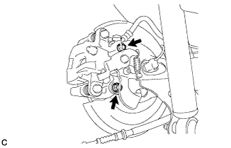
Remove the 2 bolts, and separate the rear disc brake caliper assembly.
Note
Use wire or an equivalent tool to keep the brake caliper from hanging down by the flexible hose.
-
-
REMOVE REAR DISC
-
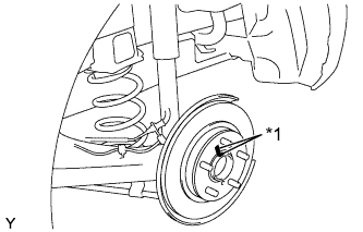
Text in Illustration *1 Matchmark Remove the rear disc.
Tech Tips
Place matchmarks on the disc and axle hub.
-
-
REMOVE REAR AXLE HUB AND BEARING ASSEMBLY
-
Remove the rear axle hub and bearing assembly Click here.
Tech Tips
-
If the sensor rotor needs to be replaced, replace it together with the rear axle hub and bearing assembly.
-
The rear speed sensor is a component of the rear axle hub and bearing assembly. If the sensor malfunctions, replace the rear axle hub and bearing assembly.
-
-