YAW RATE AND ACCELERATION SENSOR REMOVAL

Note
While the battery is connected, even if the power switch is off, the brake control system activates when the brake pedal is depressed or any door courtesy switch turns on. Therefore, when servicing the brake system components, do not operate the brake pedal or open/close the doors while the battery is connected.
-
PRECAUTION (w/ Navigation System for HDD)
Note
After the power switch is turned off, the display and navigation module display (HDD navigation system) records various types of memory and settings. As a result, after turning the power switch off, make sure to wait at least 60 seconds before disconnecting the cable from the negative (-) battery terminal.
-
REMOVE REAR NO. 2 FLOOR BOARD
-

Disengage the 2 guides <A> as shown in the illustration.
-
Disengage the 3 guides <B> and remove the rear No. 2 floor board.
-
-
REMOVE REAR DECK FLOOR BOX
-
Remove the rear deck floor box.
-
-
REMOVE REAR NO. 3 FLOOR BOARD
-

Disengage the 2 guides and remove the rear No. 3 floor board.
-
-
DISCONNECT CABLE FROM NEGATIVE BATTERY TERMINAL
Note
When disconnecting the cable, some systems need to be initialized after the cable is reconnected Click here.
-
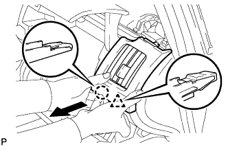
REMOVE INTEGRATION CONTROL AND PANEL ASSEMBLY
-
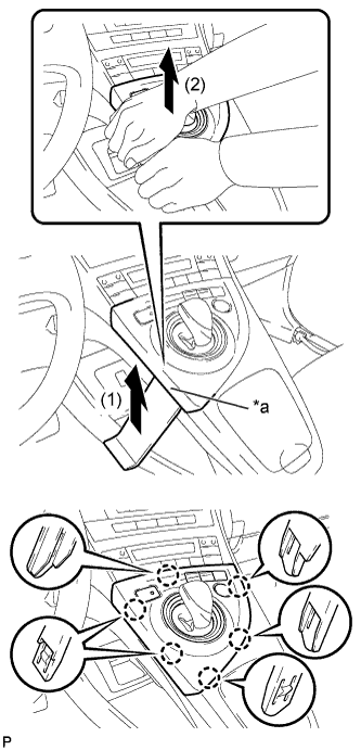
Text in Illustration *a Lift slightly Using a moulding remover, slightly lift the panel at the position shown in the illustration.
-
Pull the integration control and panel assembly in the direction indicated by the arrow to disengage the 6 claws.
-
Disconnect each connector and remove the integration control and panel assembly.
-
-
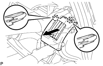
REMOVE LOWER CENTER INSTRUMENT CLUSTER FINISH PANEL SUB-ASSEMBLY
-
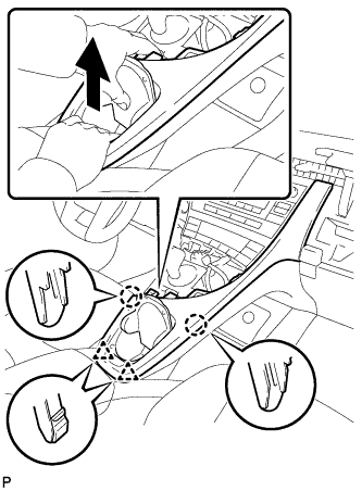
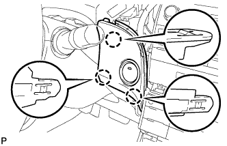
Pull the lower center instrument cluster finish panel sub-assembly in the direction indicated by the arrow to disengage the 2 claws and 2 clips.
-
Pull the lower center instrument cluster finish panel sub-assembly in the direction indicated by the arrow to disengage the 5 claws and remove the lower center instrument cluster finish panel sub-assembly.
-
-
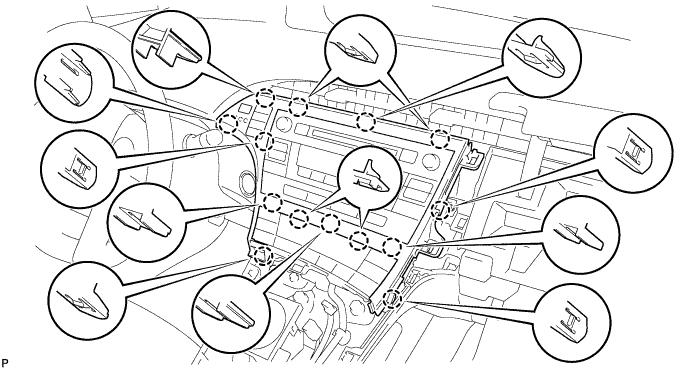
REMOVE INSTRUMENT CLUSTER FINISH PANEL GARNISH
-
Disengage the 14 claws.
-
Disconnect the connector and remove the instrument cluster finish panel garnish.
-
-
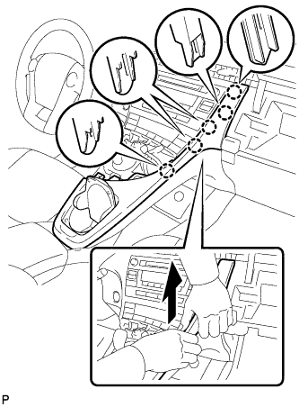
REMOVE UPPER INSTRUMENT PANEL FINISH PANEL SUB-ASSEMBLY
-
Disengage the 3 claws.
-
Disconnect the connector and remove the upper instrument panel finish panel sub-assembly.
-
-
REMOVE CENTER INSTRUMENT CLUSTER FINISH PANEL SUB-ASSEMBLY (w/o Radio Receiver)
-
Disengage the 4 claws and remove the center instrument cluster finish panel sub-assembly.
-
-
REMOVE RADIO TUNER OPENING COVER WITH BRACKET (w/o Radio Receiver)
-
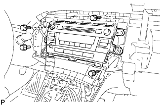
Remove the 4 bolts <B> and radio tuner opening cover with bracket.
-
-
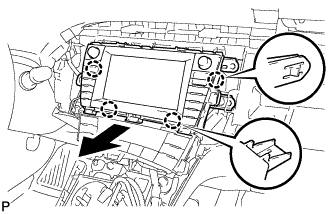
REMOVE RADIO RECEIVER WITH BRACKET (w/o Navigation System)
-
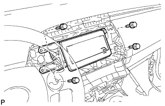
Remove the 4 bolts.
-
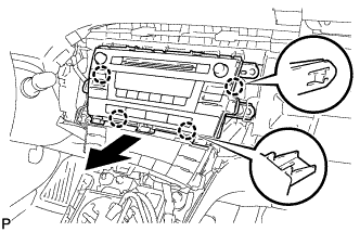
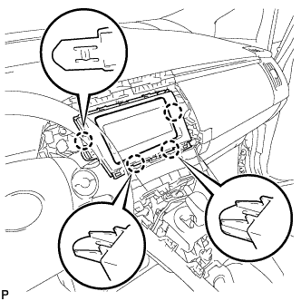
Disengage the 4 claws as shown in the illustration.
-
Disconnect each connector and remove the radio receiver with bracket.
-
-
REMOVE NAVIGATION RECEIVER WITH BRACKET (w/ Navigation System)
-
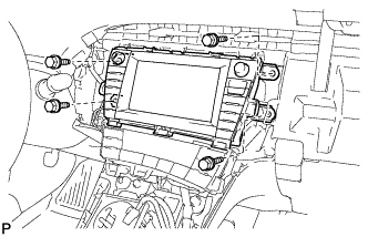
Remove the 4 bolts.
-
Disengage the 4 claws and remove the navigation receiver assembly with bracket as shown in the illustration.
-
Disconnect each connector.
-
-
REMOVE NO. 1 SIDE DEFROSTER NOZZLE
-
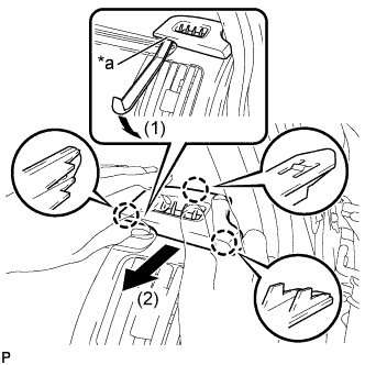
Text in Illustration *a Lift slightly Using a moulding remover, slightly lift the panel at the position shown in the illustration.
-
Pull the No. 1 side defroster nozzle in the direction indicated by the arrow to disengage the 3 claws and remove the No. 1 side defroster nozzle.
-
-
REMOVE NO. 2 INSTRUMENT PANEL REGISTER ASSEMBLY
-
Pull the No. 2 instrument panel register in the direction indicated by the arrow to disengage the claw and clip.
-
Pull the No. 2 instrument panel register in the direction indicated by the arrow to disengage the 2 claws and remove the No. 2 instrument panel register.
-
-
REMOVE GLOVE COMPARTMENT DOOR
-
Open the glove compartment door assembly.
-
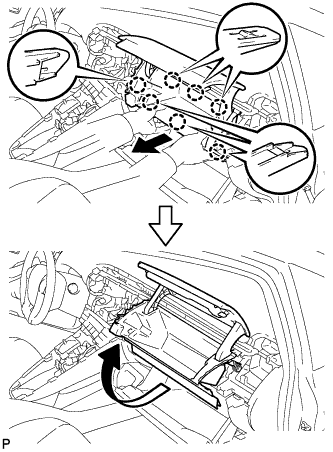
Pull the glove compartment door in the direction indicated by the arrow to disengage the 7 claws.
-
Pull the glove compartment door in the direction indicated by the arrow to remove the glove compartment door.
-
-
REMOVE REAR CONSOLE BOX ASSEMBLY
Tech Tips
Refer to the procedure up to Remove Rear Console Box Assembly Click here.
-
REMOVE ELECTRICAL KEY OSCILLATOR
-
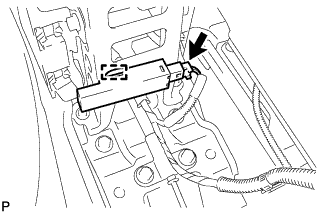
Disconnect the connector.
-
Disengage the clamp and remove the electrical key oscillator.
Note
Be careful when removing the electrical key oscillator. If the oscillator is dropped, replace it with a new one.
-
-
REMOVE NO. 2 CONSOLE BOX MOUNTING BRACKET
-
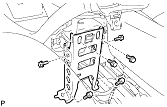
Remove the 6 bolts <B> and No. 2 console box mounting bracket.
-
-
REMOVE FRONT NO. 1 CONSOLE BOX INSERT
-
Pull the front No. 1 console box insert in the direction indicated by the arrow to disengage the 4 claws and guide, and remove the front No. 1 console box insert.
-
-
REMOVE FRONT NO. 2 CONSOLE BOX INSERT
-
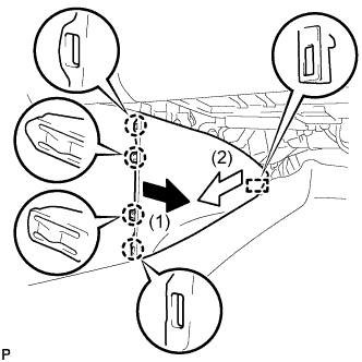
Pull the front No. 2 console box insert in the direction indicated by the arrow to disengage the 4 claws and guide, and remove the front No. 2 console box insert.
-
-
REMOVE BOX BOTTOM MAT
-
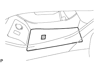
Disengage the fastener and remove the box bottom mat.
-
-
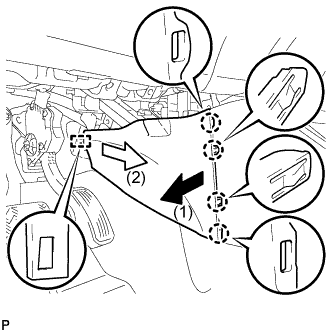
SEPARATE CONSOLE BOX ASSEMBLY
-
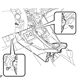
Remove the bolt <B> and 2 clips.
-
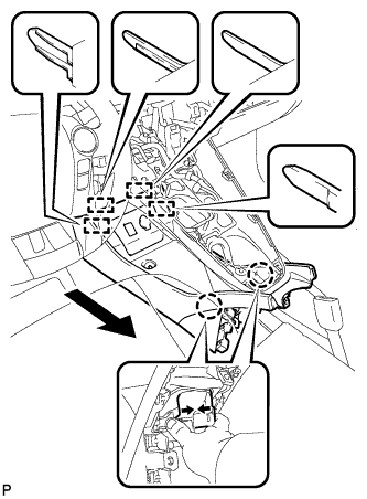
While pushing the parts shown in the illustration inward, pull the console box assembly in the direction indicated by the arrow to disengage the 2 claws and 4 guides.
-
Disconnect the connector and separate the console box assembly.
-
-
REMOVE AIR CONDITIONING CONTROL ASSEMBLY
-
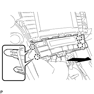
Disengage the 4 claws and remove the air conditioning control assembly as shown in the illustration.
-
Disconnect the connector.
Note
Since the connectors for the air conditioning control assembly and the integration control and panel sub-assembly are the same shape, mark them so that they will not be reconnected incorrectly.
-
-
REMOVE SHIFT LOCK CONTROL UNIT ASSEMBLY
-
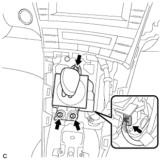
Disconnect the connector from the shift lock control unit assembly.
-
Remove the 3 nuts and shift lock control unit assembly.
-
-
REMOVE UPPER INSTRUMENT PANEL FINISH PANEL ASSEMBLY
-
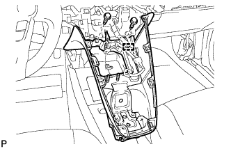
Disengage the clamp.
-
Remove the 2 bolts <A>.
-
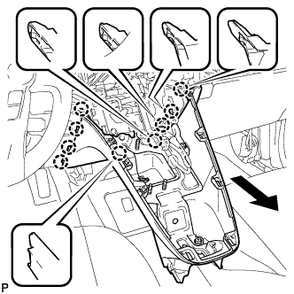
Pull the upper instrument panel finish panel assembly in the direction indicated by the arrow to disengage the 9 claws and remove the upper instrument panel finish panel assembly.
-
-
REMOVE CONSOLE BOX ASSEMBLY
-
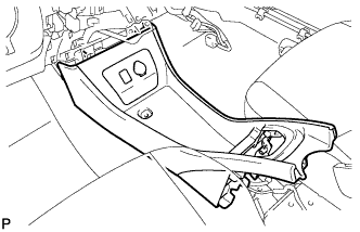
Remove the console box assembly.
-
-
REMOVE YAW RATE AND ACCELERATION SENSOR
-
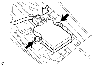
Remove the 2 bolts and yaw rate and acceleration sensor.
-
Disconnect the connector from the yaw rate and acceleration sensor.
-