REAR AXLE BEAM INSTALLATION

-
INSTALL REAR AXLE CARRIER BUSHING LH
-
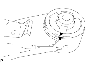
Text in Illustration *1 Matchmark Align the arrow mark on a new rear axle carrier bushing LH with the matchmark on the rear axle beam assembly and temporarily install the rear axle carrier bushing LH to the rear axle beam assembly. (If the rear axle beam assembly is reused.)
Note
Be sure to install the rear axle carrier bushing in the same direction as it was before removal.
The rear axle carrier bushing has to be installed in a specific direction.
-
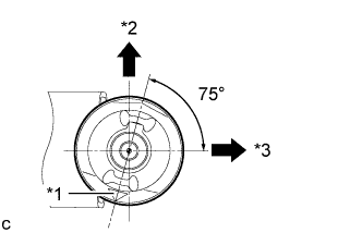
Text in Illustration *1 Mark *2 Upper Side of the Vehicle *3 Front of the Vehicle Temporarily install the new rear axle carrier bushing LH as shown in the illustration.
Note
Be sure to install the rear axle carrier bushing in the same direction as it was before removal.
The rear axle carrier bushing has to be installed in a specific direction.
-
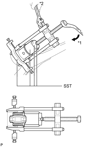
Text in Illustration *1 Turn *2 Hold Using SST, install the rear axle carrier bushing LH to the rear axle beam assembly.
- SST
- 09710-30012 ( 09710-04101 )
- 09950-40011 ( 09951-04020, 09952-04010, 09953-04030, 09954-04020, 09955-04051, 09957-04010, 09958-04011 )
- 09950-60010 ( 09951-00620 )
Note
-
Do not damage the rubber portion when installing the rear axle carrier bushing.
-
Apply grease to the threads and tip of the SST center bolt before use.
-
-
INSTALL REAR AXLE CARRIER BUSHING RH
Tech Tips
Perform the same procedure as for the LH side.
-
TEMPORARILY TIGHTEN REAR AXLE BEAM ASSEMBLY
-
Slowly jack up the rear axle beam assembly with a jack using 2 wooden blocks and 2 attachments or equivalent tools and temporarily install the rear axle beam assembly to the body with the 2 bolts (B).
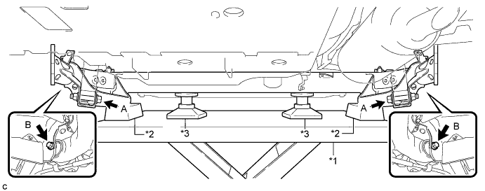
Text in Illustration *1 Jack *3 Attachment *2 Wooden Block - - Note
Make sure to secure the rear axle beam assembly to prevent it from dropping.
-
Temporarily tighten the rear axle beam assembly to the rear shock absorber assemblies LH and RH with the 2 bolts (A) and 2 nuts.
Note
Since the stopper nuts are used, turn the bolts.
Tech Tips
Insert the bolts with the threaded end facing the outside of the vehicle.
-
-
INSTALL REAR UPPER COIL SPRING INSULATOR LH
-
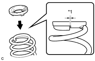
Text in Illustration *1 10 mm or less Install the rear upper coil spring insulator LH to the rear coil spring LH.
Note
Install the rear upper coil spring insulator so that the dimension between the stopper and the upper end of the rear coil spring is 10 mm (0.394 in.) or less.
-
-
INSTALL REAR UPPER COIL SPRING INSULATOR RH
Tech Tips
Perform the same procedure as for the LH side.
-
INSTALL REAR LOWER COIL SPRING INSULATOR LH
-
INSTALL REAR LOWER COIL SPRING INSULATOR RH
-
INSTALL REAR COIL SPRING LH
-
Support the spring seat of the rear axle beam assembly using 2 jacks and 2 wooden blocks.
Text in Illustration *1 Jack *2 Wooden Block -
Remove the 2 bolts while holding the 2 nuts and separate the rear axle beam assembly from the rear shock absorber assemblies LH and RH.
Note
Since the stopper nuts are used, turn the bolts.
-
Slowly lower the rear axle beam assembly using 2 jacks and 2 wooden blocks.
-
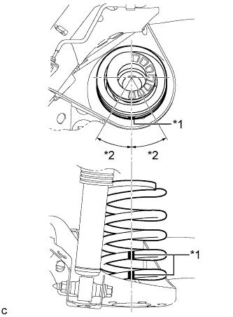
Text in Illustration *1 Identification Mark *2 30° or less Set the rear coil spring LH to the rear axle beam assembly.
Note
Set the rear coil spring so that the identification marks are positioned as shown in the illustration.
-
Slowly jack up the rear axle beam assembly using 2 jacks and 2 wooden blocks and temporarily install the rear axle beam assembly and rear coil spring LH with the 2 bolts and 2 nuts.
Text in Illustration *1 Jack *2 Wooden Block Note
Since the stopper nuts are used, turn the bolts.
Tech Tips
Insert the bolt with the threaded end facing the outside of the vehicle.
-
-
INSTALL REAR COIL SPRING RH
Tech Tips
Perform the same procedure as for the LH side.
-
INSTALL REAR HEIGHT CONTROL SENSOR SUB-ASSEMBLY RH (w/ Height Control Sensor)
-
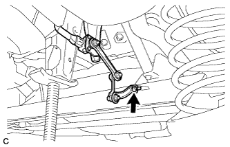
Install the rear height control sensor sub-assembly RH to the rear axle beam assembly with the bolt.
- Torque:
- 8.0 N*m { 82 kgf*cm, 71 in.*lbf }
-
-
INSTALL REAR AXLE HUB AND BEARING ASSEMBLY LH
-
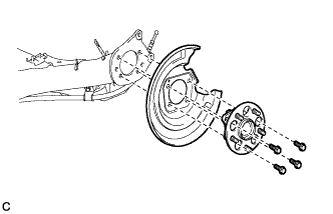
Install the rear axle hub and bearing assembly and rear disc brake dust cover to the rear axle beam assembly with the 4 bolts.
- Torque:
- 90 N*m { 918 kgf*cm, 66 ft.*lbf }
-
-
INSTALL REAR AXLE HUB AND BEARING ASSEMBLY RH
Tech Tips
Perform the same procedure as for the LH side.
-
INSTALL REAR NO. 4 BRAKE TUBE
-
Install the rear No. 4 brake tube to the rear axle beam assembly with the nut.
- Torque:
- 8.5 N*m { 87 kgf*cm, 75 in.*lbf }
-
-
INSTALL REAR NO. 3 BRAKE TUBE
Tech Tips
Perform the same procedure as for the rear No. 4 brake tube.
-
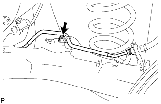
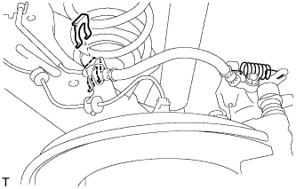
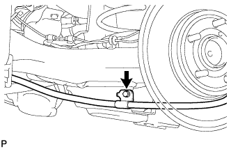
CONNECT REAR BRAKE TUBE FLEXIBLE HOSE
-
for LH Side
Text in Illustration *1 LH Side *2 RH Side
-
Install the rear brake tube flexible hose with the bolt.
- Torque:
- 19 N*m { 194 kgf*cm, 14 ft.*lbf }
-
-
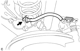
for RH Side
-
Install the rear brake tube flexible hose with a new clip.
Note
Install the clip as far as it will go.
-
-
Using a union nut wrench, connect the 2 brake lines to the rear brake tube flexible hose.
- Torque:
- 15 N*m { 155 kgf*cm, 11 ft.*lbf }
Note
-
Do not bend or damage the brake line.
-
Do not allow any foreign matter such as dirt and dust to enter the brake line from the connecting points.
-
Use the formula to calculate special torque values for situations where the union nut wrench is combined with a torque wrench Click here.
-
-
INSTALL REAR DISC (for LH Side)
-
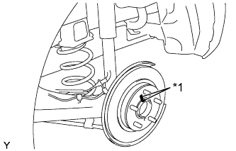
Text in Illustration *1 Matchmark Align the matchmarks of the disc and axle hub, and install the disc.
Note
When replacing the disc with a new one, select the installation position where the rear disc has minimal runout.
-
-
INSTALL REAR DISC (for RH Side)
Tech Tips
Perform the same procedure as for the LH side.
-
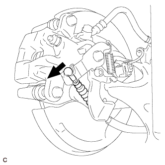
INSTALL REAR DISC BRAKE CALIPER ASSEMBLY LH
-
Install the rear disc brake caliper assembly LH with rear flexible hose LH with the 2 bolts.
- Torque:
- 57 N*m { 585 kgf*cm, 42 ft.*lbf }
-
Connect the rear flexible hose LH to the rear axle beam assembly with a new clip.
Note
Install the clip as far as it will go.
-
Using a union nut wrench, connect the brake line to the rear flexible hose LH while holding the rear flexible hose LH with a wrench.
- Torque:
- 15 N*m { 155 kgf*cm, 11 ft.*lbf }
Note
-
Do not bend or damage the brake line.
-
Do not allow any foreign matter such as dirt and dust to enter the brake line from the connecting points.
-
Use the formula to calculate special torque values for situations where the union nut wrench is combined with a torque wrench Click here.
-
-
INSTALL REAR DISC BRAKE CALIPER ASSEMBLY RH
Tech Tips
Perform the same procedure as for the LH side.
-
INSTALL NO. 3 PARKING BRAKE CABLE ASSEMBLY
-
Install the No. 3 parking brake cable assembly to the rear axle beam assembly with the bolt.
- Torque:
- 6.0 N*m { 61 kgf*cm, 53 in.*lbf }
-
-
INSTALL NO. 2 PARKING BRAKE CABLE ASSEMBLY
Tech Tips
Perform the same procedure as for the No. 3 parking brake cable assembly.
-
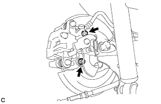
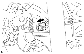
CONNECT NO. 3 PARKING BRAKE CABLE ASSEMBLY
-
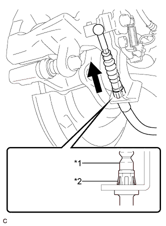
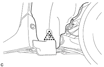
Text in Illustration *1 No. 3 Parking Brake Cable Assembly *2 Clip Install the No. 3 parking brake cable assembly to the rear disc brake cylinder assembly.
Tech Tips
Be sure to engage the No. 3 parking brake cable assembly clip onto the rear disc brake cylinder assembly as shown in the illustration.
-
Connect the No. 3 parking brake cable assembly to the rear disc brake cylinder assembly.
-
-
CONNECT NO. 2 PARKING BRAKE CABLE ASSEMBLY
Tech Tips
Perform the same procedure as for the LH side.
-
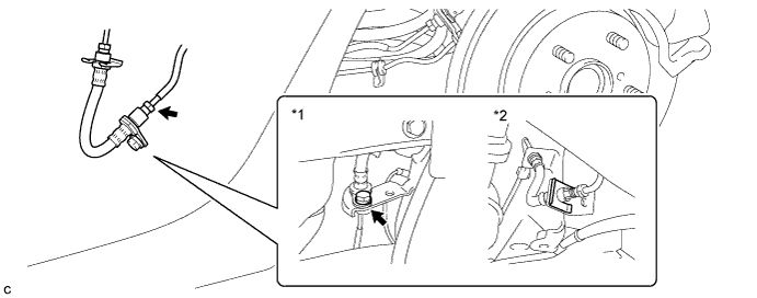
INSTALL REAR SPEED SENSOR WIRE (for LH Side)
-
Install the rear speed sensor wire to the rear axle beam assembly with the nut and 2 clamps.
- Torque:
- 8.5 N*m { 87 kgf*cm, 75 in.*lbf }
Note
Do not twist the rear speed sensor wire when installing it.
-
-
INSTALL REAR SPEED SENSOR WIRE (for RH Side)
Tech Tips
Perform the same procedure as for the LH side.
-
CONNECT REAR SPEED SENSOR WIRE (for LH Side)
-
Connect the rear speed sensor wire connector to the rear speed sensor.
-
-
CONNECT REAR SPEED SENSOR WIRE (for RH Side)
Tech Tips
Perform the same procedure as for the LH side.
-
INSTALL REAR SUSPENSION BRACE SUB-ASSEMBLY
-
Install the rear suspension brace sub-assembly with the 4 bolts and clip.
- Torque:
- 54 N*m { 551 kgf*cm, 40 ft.*lbf }
-
-
INSTALL REAR FLOOR SIDE MEMBER COVER LH
-
Install the rear floor side member cover LH with the nut and 2 bolts.
-
-
INSTALL REAR FLOOR SIDE MEMBER COVER RH
-
Engage the clip to temporarily install the rear floor side member cover RH.
-
Install the rear floor side member cover RH with the 3 bolts.
-
-
ADJUST PARKING BRAKE
-
INSTALL LOWER INSTRUMENT PANEL FINISH PANEL ASSEMBLY (for LHD)
-
Connect each connector.
-
Engage the clamp.
-
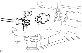
Engage the 2 guides and claw to connect the hood lock control cable.
-
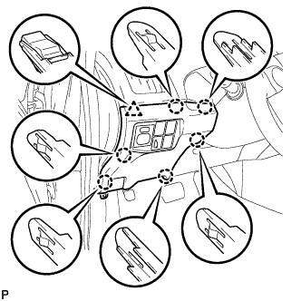
Engage the 6 claws and clip.
-
Install the lower instrument panel finish panel assembly with the screw <C>.
-
-
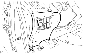
INSTALL COWL SIDE TRIM SUB-ASSEMBLY LH (for LHD)
-
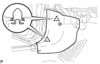
Engage the 2 clips.
-
Install the cowl side trim board LH with the clip.
-
-
INSTALL FRONT DOOR SCUFF PLATE LH (for LHD)
-
Engage the 10 claws to install the front door scuff plate LH.
-
-
INSTALL NO. 1 INSTRUMENT PANEL UNDER COVER SUB-ASSEMBLY (for RHD)
-
Connect each connector.
-
Engage the guide and 2 claws.
-
Install the No. 1 instrument panel under cover sub-assembly with the screw <D>.
-
-
FILL RESERVOIR WITH BRAKE FLUID
-
CONNECT CABLE TO NEGATIVE BATTERY TERMINAL
Note
When disconnecting the cable, some systems need to be initialized after the cable is reconnected Click here.
-
INSTALL REAR NO. 3 FLOOR BOARD
-

Engage the 2 guides to install the rear No. 3 floor board.
-
-
INSTALL REAR DECK FLOOR BOX
-
Install the rear deck floor box.
-
-
INSTALL REAR NO. 2 FLOOR BOARD
-

Engage the 3 guides <A>.
-
Engage the 2 guides <B> and install the rear No. 2 floor board as shown in the illustration.
-
-
BLEED BRAKE LINE
-
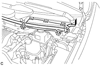
Remove the center cowl top ventilator cover.
-
Slide the hood to cowl top seal and disengage the claw.
-
Disengage the 2 claws and 3 guides, and remove the center cowl top ventilator cover.
-
-
Bleed brake line.
-
Remove the brake master cylinder reservoir filler cap assembly.
-
Add brake fluid into the reservoir between MAX and MIN level on the brake fluid reservoir.
Brake fluid SAE J1703 or FMVSS No. 116 DOT3 -
Connect the intelligent tester to the DLC3 and turn the power switch on (IG).
-
Turn the intelligent tester on and enter the following menus: Chassis / ABS/VSC/TRC / Air Bleeding.
-
Select the "Usual air bleeding" on the intelligent tester display, and bleed air from the brake fluid following the instructions on the intelligent tester.
-
After air bleeding, tighten each bleeder plug.
- Torque:
- front bleeder plug
- 8.3 N*m { 85 kgf*cm, 73 in.*lbf }
- rear bleeder plug
- 11 N*m { 112 kgf*cm, 8 ft.*lbf }
-
Clear the DTCs Click here.
-
Turn the intelligent tester off and turn the power switch off.
-
-
Inspect for brake fluid leaks.
-
Install the brake master cylinder reservoir filler cap.
-
Install the center cowl top ventilator cover.
-
Engage the 2 claws and 3 guides to install the center cowl top ventilator cover.
-
Slide the hood to cowl top seal to engage the claw.
-
-
-
INSTALL REAR WHEELS
- Torque:
- 103 N*m { 1050 kgf*cm, 76 ft.*lbf }
-
STABILIZE SUSPENSION
-
Lower the vehicle.
-
Bounce the vehicle up and down several times to stabilize the suspension.
-
-
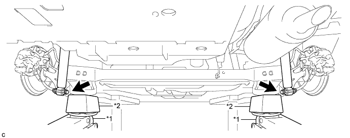
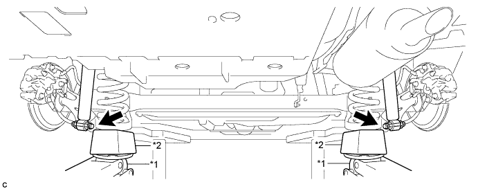
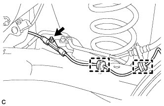
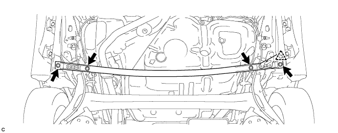
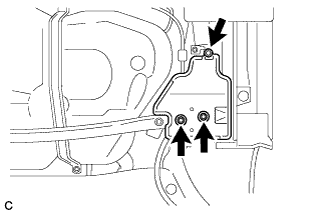
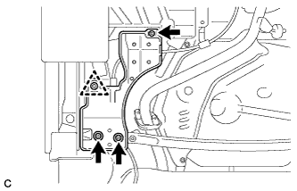
FULLY TIGHTEN REAR AXLE BEAM ASSEMBLY
-
Text in Illustration *1 LH Side *2 RH Side Fully tighten the 2 bolts.
- Torque:
- 135 N*m { 1377 kgf*cm, 100 ft.*lbf }
Note
The final torque must be applied under the standard vehicle height conditions.
-
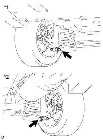
Text in Illustration *1 LH Side *2 RH Side Fully tighten the 2 bolts.
- Torque:
- 90 N*m { 918 kgf*cm, 66 ft.*lbf }
Note
-
Since the stopper nut are used, turn the bolts.
-
The final torque must be applied under the standard vehicle height conditions.
-
-
INSTALL REAR WHEEL HOUSE LINER LH
-
Install the rear wheel house liner LH with the clip.
-
-
INSTALL REAR WHEEL HOUSE LINER RH
Tech Tips
Perform the same procedure as for the LH side.
-
INSPECT REAR WHEEL ALIGNMENT
-
PLACE FRONT WHEELS FACING STRAIGHT AHEAD
-
PERFORM YAW RATE AND ACCELERATION SENSOR CALIBRATION
-
CHECK FOR SPEED SENSOR SIGNAL
-
PERFORM INITIALIZATION (w/ Height Control Sensor)
Note
Some systems need to be initialized after the rear height control sensor sub-assembly RH is replaced Click here.