REAR AXLE BEAM REMOVAL

-
PRECAUTION (w/ Navigation System for HDD)
Note
After the power switch is turned off, the display and navigation module display (HDD navigation system) records various types of memory and setting. As a result, after turning the power switch off, make sure to wait at least 60 seconds before disconnecting the cable from the negative (-) battery terminal.
-
REMOVE REAR NO. 2 FLOOR BOARD
-

Disengage the 2 guides <A> as shown in the illustration.
-
Disengage the 3 guides <B> and remove the rear No. 2 floor board.
-
-
REMOVE REAR DECK FLOOR BOX
-
Remove the rear deck floor box.
-
-
REMOVE REAR NO. 3 FLOOR BOARD
-

Disengage the 2 guides and remove the rear No. 3 floor board.
-
-
DISABLE BRAKE CONTROL
-
Wait at least 2 minutes after the power switch off.
Note
When the brake pedal is depressed or the door courtesy switch is turned on even if the power switch is off, the brake control system activates. Therefore do not depress the brake pedal or open/close the doors until the reservoir level switch connector is disconnected.
-
Disconnect the reservoir level switch connector with the parking brake applied.
-
Disconnect the cable from the negative (-) battery terminal.
Note
When disconnecting the cable, some systems need to be initialized after the cable is reconnected Click here.
-
Depress the brake pedal 40 times or more to return all the fluid in the accumulator back to the reservoir.
-
Check that the brake pedal can not be further depressed.
-
Release the parking brake.
-
-
REMOVE REAR WHEELS
-
REMOVE FRONT DOOR SCUFF PLATE LH (for LHD)
-
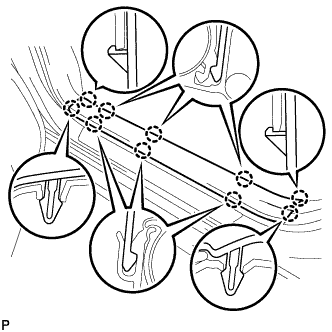
Disengage the 10 claws and remove the front door scuff plate LH.
-
-
REMOVE COWL SIDE TRIM SUB-ASSEMBLY LH (for LHD)
-
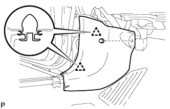
Remove the clip.
-
Disengage the 2 clips and remove the cowl side trim sub-assembly LH.
-
-
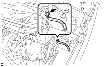
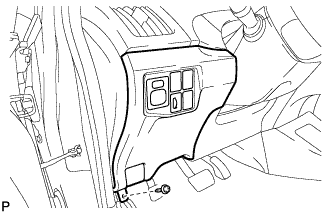
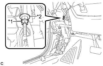
REMOVE LOWER INSTRUMENT PANEL FINISH PANEL ASSEMBLY (for LHD)
-
Remove the screw <C>.
-
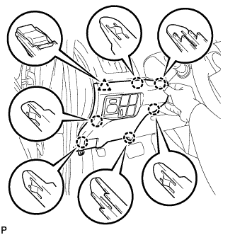
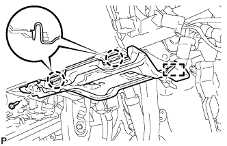
Disengage the 6 claws and clip as shown in the illustration.
-
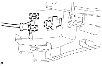
Disengage the claw and 2 guides and disconnect the hood lock control cable.
-
Disconnect each connector and clamp, and remove the lower instrument panel finish panel assembly.
-
-
REMOVE NO. 1 INSTRUMENT PANEL UNDER COVER SUB-ASSEMBLY (for RHD)
-
Remove the screw <D>.
-
Disengage the 2 claws and guide.
-
Disconnect each connector and remove the No. 1 instrument panel under cover sub-assembly.
-
-
LOOSEN PARKING BRAKE CABLE
-
Completely release the parking brake pedal.
-
Text in Illustration *1 Lock Nut *2 Adjusting Nut Loosen the lock nut and adjusting nut to completely release the parking brake cable.
-
-
DRAIN BRAKE FLUID
Note
If brake fluid leaks onto any painted surface, immediately wash it off.
-
REMOVE REAR FLOOR SIDE MEMBER COVER LH
-
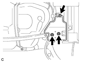
Remove the nut, 2 bolts and rear floor side member cover LH.
-
-
REMOVE REAR FLOOR SIDE MEMBER COVER RH
-
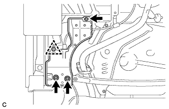
Remove the 3 bolts.
-
Disengage the clip and remove the rear floor side member cover RH.
-
-
REMOVE REAR SUSPENSION BRACE SUB-ASSEMBLY
-
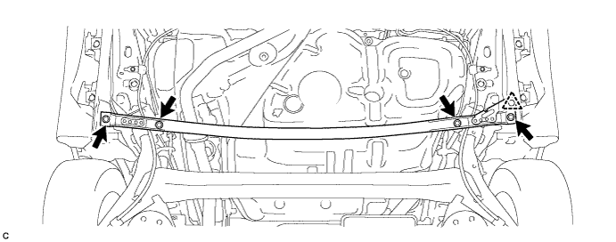
Remove the 4 bolts.
-
Disengage the clip and remove the rear suspension brace sub-assembly.
-
-
DISCONNECT REAR SPEED SENSOR WIRE (for LH Side)
-
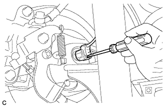
Using a screwdriver, disconnect the connector from the rear speed sensor.
Note
Be careful not to damage the rear speed sensor.
-
-
DISCONNECT REAR SPEED SENSOR WIRE (for RH Side)
Tech Tips
Perform the same procedure as for the LH side.
-
SEPARATE REAR SPEED SENSOR WIRE (for LH Side)
-
Remove the nut and separate the 2 clamps and rear speed sensor wire.
-
-
SEPARATE REAR SPEED SENSOR WIRE (for RH Side)
Tech Tips
Perform the same procedure as for the LH side.
-
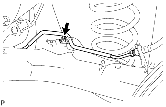
DISCONNECT NO. 3 PARKING BRAKE CABLE ASSEMBLY
-
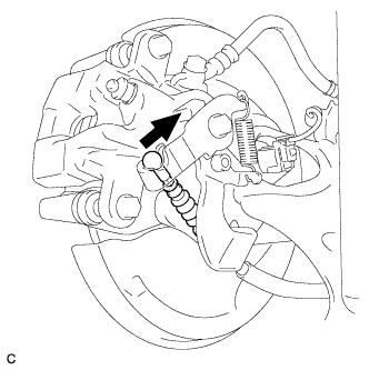
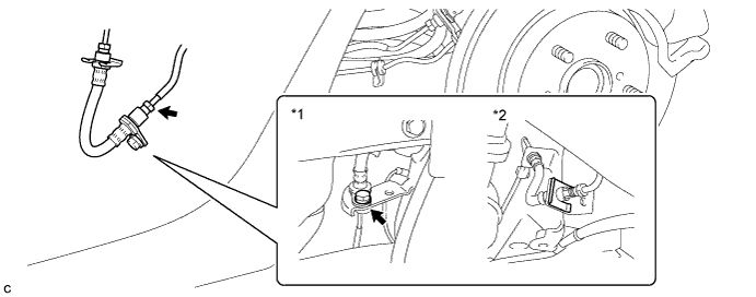
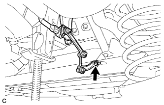
Separate the No. 3 parking brake cable assembly from the rear disc brake cylinder assembly.
-
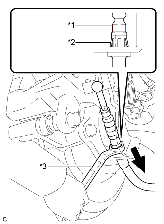
Text in Illustration *1 No. 3 Parking Brake Cable Assembly *2 Clip *3 Offset Wrench (14 mm) Separate the No. 3 parking brake cable assembly from the rear disc brake cylinder assembly.
Tech Tips
Insert an offset wrench (14 mm) at the base of the No. 3 parking brake cable assembly as shown in the illustration to disengage the clip. Pull out the No. 3 parking brake cable assembly from the rear disc brake cylinder assembly.
-
-
DISCONNECT NO. 2 PARKING BRAKE CABLE ASSEMBLY
Tech Tips
Perform the same procedure as for the No. 3 parking brake cable assembly.
-
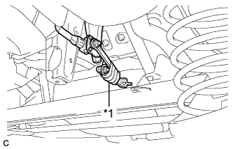
SEPARATE NO. 3 PARKING BRAKE CABLE ASSEMBLY
-
Remove the bolt and separate the No. 3 parking brake cable assembly.
-
-
SEPARATE NO. 2 PARKING BRAKE CABLE ASSEMBLY
Tech Tips
Perform the same procedure as for the No. 3 parking brake cable assembly.
-
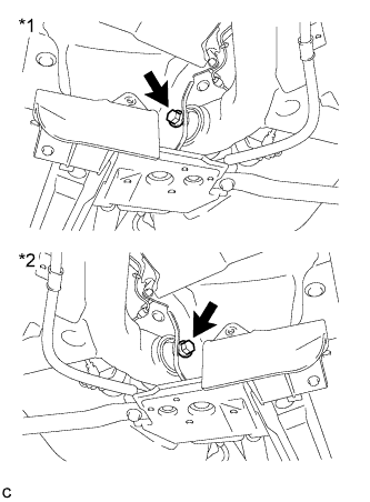
SEPARATE REAR BRAKE TUBE FLEXIBLE HOSE
-
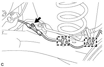
Using a union nut wrench, disconnect the 2 brake lines while holding the rear brake tube flexible hose with a wrench.
Text in Illustration *1 LH Side *2 RH Side Note
-
Do not bend or damage the brake line.
-
Do not allow any foreign matter such as dirt or dust to enter the brake line from the connecting points.
-
-
for LH Side
-
Remove the bolt and separate the rear brake tube flexible hose from the rear axle beam assembly.
-
-
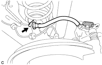
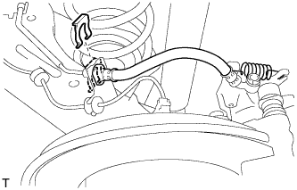
for RH Side
-
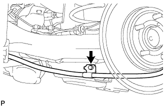
Remove the clip and separate the rear brake tube flexible hose from the rear axle beam assembly.
-
-
-
REMOVE REAR DISC BRAKE CALIPER ASSEMBLY LH
-
Using a union nut wrench, disconnect the brake line while holding the rear flexible hose LH with a wrench.
Note
-
Do not bend or damage the brake line.
-
Do not allow any foreign matter such as dirt or dust to enter the brake line from the connecting points.
-
-
Remove the clip and separate the rear flexible hose LH.
-
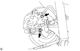
Remove the 2 bolts and rear disc brake caliper assembly LH with rear flexible hose LH.
-
-
REMOVE REAR DISC BRAKE CALIPER ASSEMBLY RH
Tech Tips
Perform the same procedure as for the LH side.
-
REMOVE REAR DISC (for LH Side)
-
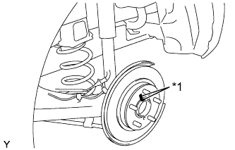
Text in Illustration *1 Matchmark Remove the rear disc.
Tech Tips
Place matchmarks on the disc and axle hub.
-
-
REMOVE REAR DISC (for RH Side)
Tech Tips
Perform the same procedure as for the LH side.
-
REMOVE REAR NO. 4 BRAKE TUBE
-
Remove the nut and rear No. 4 brake tube from the rear axle beam assembly.
-
-
REMOVE REAR NO. 3 BRAKE TUBE
Tech Tips
Perform the same procedure as for the rear No. 4 brake tube.
-
REMOVE REAR AXLE HUB AND BEARING ASSEMBLY LH
-
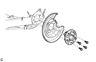
Remove the 4 bolts, rear axle hub and bearing assembly and rear disc brake dust cover from the rear axle beam assembly.
-
-
REMOVE REAR AXLE HUB AND BEARING ASSEMBLY RH
Tech Tips
Perform the same procedure as for the LH side.
-
SEPARATE REAR WHEEL HOUSE LINER LH
-
Remove the clip and turn back the rear wheel house liner LH to separate the rear wheel house liner LH.
-
-
SEPARATE REAR WHEEL HOUSE LINER RH
Tech Tips
Perform the same procedure as for the LH side.
-
SEPARATE REAR HEIGHT CONTROL SENSOR SUB-ASSEMBLY RH (w/ Height Control Sensor)
-
Remove the bolt and separate the rear height control sensor sub-assembly RH from the rear axle beam assembly.
-
Text in Illustration *1 Vinyl Tape Using a vinyl tape, secure the rear height control sensor sub-assembly RH as shown in the illustration.
-
-
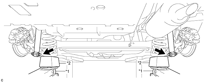
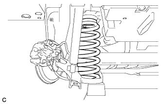
REMOVE REAR COIL SPRING LH
-
Text in Illustration *1 LH Side *2 RH Side Loosen the 2 bolts.
Note
Do not remove the bolts.
-
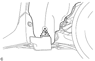
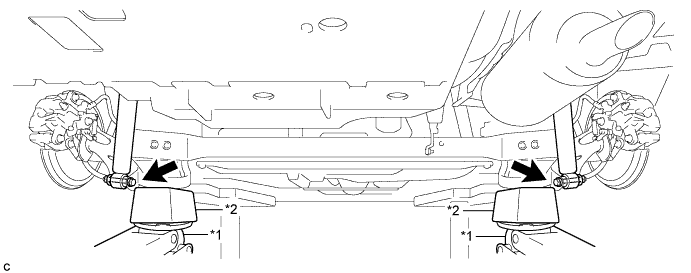
Support the spring seat of the rear axle beam assembly using 2 jacks and 2 wooden blocks.
Text in Illustration *1 Jack *2 Wooden Block CAUTION:
Do not jack up the rear axle beam assembly too high as the vehicle may fall.
Tech Tips
Support the rear shock absorber at a position where it compresses by approximately 20 to 30 mm (0.787 to 1.18 in.).
-
Remove the 2 bolts while holding the 2 nuts and separate the rear axle beam assembly from the rear shock absorber assemblies LH and RH.
Note
Since the stopper nuts are used, turn the bolts.
-
Slowly lower the rear axle beam assembly using 2 jacks and 2 wooden blocks, and remove the rear coil spring LH.
Note
When moving the rear axle beam assembly beyond full rebound, make sure that the rear axle beam assembly is not out of position for more than 10 minutes.
-
Slowly jack up the rear axle beam assembly using 2 jacks and 2 wooden blocks, and temporarily tighten the rear axle beam assembly to the rear shock absorber assemblies LH and RH with the 2 bolts and 2 nuts.
Text in Illustration *1 Jack *2 Wooden Block Note
Since the stopper nuts are used, turn the bolts.
-
-
REMOVE REAR COIL SPRING RH
Tech Tips
Perform the same procedure as for the LH side.
-
REMOVE REAR UPPER COIL SPRING INSULATOR LH
-
REMOVE REAR UPPER COIL SPRING INSULATOR RH
-
REMOVE REAR LOWER COIL SPRING INSULATOR LH
-
REMOVE REAR LOWER COIL SPRING INSULATOR RH
-
REMOVE REAR AXLE BEAM ASSEMBLY
-
Support the rear axle beam assembly with a jack using 2 wooden blocks and 2 attachments or equivalent tools to replicate standard vehicle height conditions as shown in the illustration.
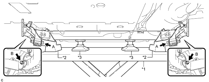
Text in Illustration *1 Jack *2 Wooden Block *3 Attachment - - Note
Make sure to secure the rear axle beam assembly to prevent it from dropping.
-
Remove the 2 bolts (A) and 2 nuts while holding the 2 nuts and separate the rear axle beam assembly from the rear shock absorber assemblies LH and RH.
Note
Since the stopper nuts are used, turn the bolts.
-
Remove the 2 bolts (B) and rear axle beam assembly.
-
-
REMOVE REAR AXLE CARRIER BUSHING LH
-
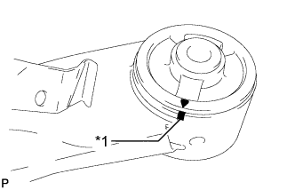
Text in Illustration *1 Matchmark Put a matchmark on the rear axle beam assembly so that the mark aligns with the arrow mark on the rear axle carrier bushing LH. (If the rear axle beam assembly is reused.)
-
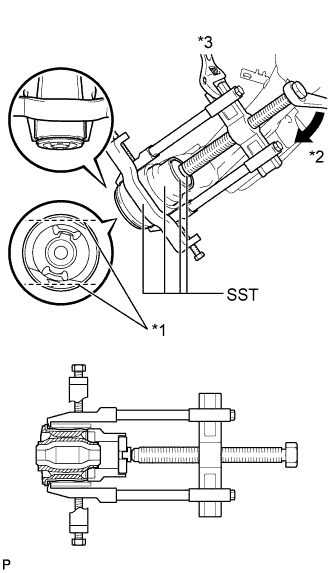
Text in Illustration *1 Bend Portion *2 Turn *3 Hold Using a chisel and hammer, bend the 2 ribs on the rear axle carrier bushing LH.
Note
When removing the rear axle carrier bushing, do not erase the matchmark on the rear axle beam assembly.
-
Using SST, remove the rear axle carrier bushing LH from the rear axle beam assembly.
- SST
- 09710-26011 ( 09710-05061 )
- 09950-40011 ( 09951-04020, 09952-04010, 09953-04030, 09954-04020, 09955-04051, 09957-04010, 09958-04011 )
- 09950-60010 ( 09951-00530 )
Note
Apply grease to the threads and tip of the SST center bolt before use.
-
-
REMOVE REAR AXLE CARRIER BUSHING RH
Tech Tips
Perform the same procedure as for the LH side.