REAR SHOCK ABSORBER REMOVAL

Tech Tips
-
Use the same procedure for the RH side and LH side.
-
The procedure listed below is for the LH side.
-
REMOVE TONNEAU COVER ASSEMBLY (w/ Tonneau Cover)
-
Remove the tonneau cover assembly.
-
-
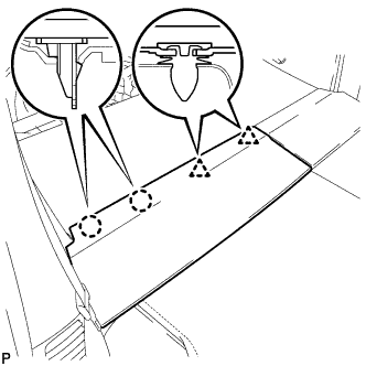
REMOVE REAR NO. 2 FLOOR BOARD
-

Disengage the 2 guides <A> as shown in the illustration.
-
Disengage the 3 guides <B> and remove the rear No. 2 floor board.
-
-
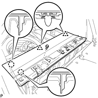
REMOVE REAR DECK FLOOR BOX
-
Remove the rear deck floor box.
-
-
REMOVE REAR NO. 4 FLOOR BOARD (for LH Side)
-
Disengage the guide and remove the rear No. 4 floor board.
-
-
REMOVE DECK FLOOR BOX LH (for LH Side)
-
Remove the clip.
-
Disengage the 2 guides and remove the deck floor box LH.
-
-
REMOVE REAR NO. 3 FLOOR BOARD (for RH Side)
-

Disengage the 2 guides and remove the rear No. 3 floor board.
-
-
REMOVE REAR NO. 1 FLOOR BOARD SUB-ASSEMBLY
-
Disengage the 2 claws and 2 clips, and remove the rear No. 1 floor board sub-assembly.
-
-
REMOVE REAR NO. 2 FLOOR BOARD SUB-ASSEMBLY
-

Disengage the claw and 2 clips, and remove the rear No. 2 floor board sub-assembly.
-
-
REMOVE REAR NO. 1 FLOOR BOARD
-
Remove the bolt.
-
Disengage the 2 claws and 2 clips, and remove the rear No. 1 floor board.
-
-
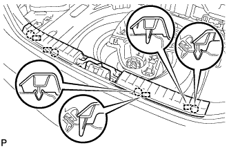
REMOVE DECK TRIM SERVICE HOLE COVER
-
Disengage the 2 claws and 3 guides, and remove the deck trim service hole cover.
-
-
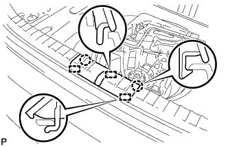
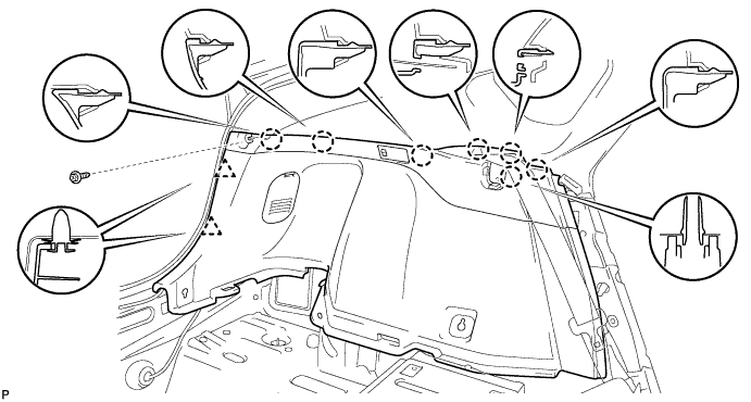
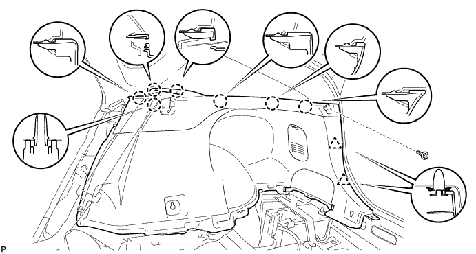
REMOVE REAR DECK TRIM COVER
-
Disengage the 4 claws and 4 guides, and remove the rear deck trim cover.
-
-
REMOVE REAR DOOR SCUFF PLATE LH (for LH Side)
-
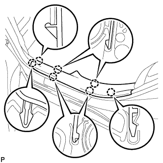
Disengage the 7 claws and remove the rear door scuff plate LH.
-
-
REMOVE REAR DOOR SCUFF PLATE RH (for RH Side)
Tech Tips
Use the same procedure described for the LH side.
-
REMOVE REAR SEAT CUSHION ASSEMBLY
-
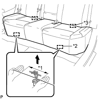
Text in Illustration *1 100 mm (3.94 in.) or less *2 Hook *3 Guide Disengage the 2 front hooks of the seat cushion from the vehicle body as shown in the illustration.
Note
Follow the instructions below carefully as the cushion frame deforms easily.
-
Choose a hook to detach first. Place your hands near the hook as shown in the illustration. Then lift the seat cushion to detach the hook.
-
Repeat the above procedure for the other hook.
-
-
Disengage the 2 guides of the seat cushion from the seatback.
-
Remove the rear seat cushion assembly.
-
-
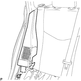
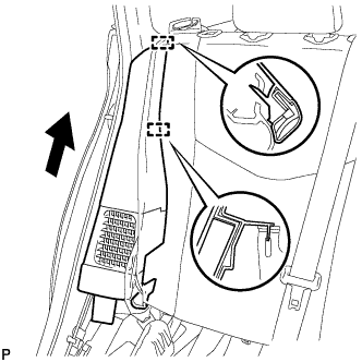
REMOVE REAR SIDE SEATBACK ASSEMBLY LH (for LH Side)
-
Remove the bolt.
-
Disengage the 2 guides and remove the rear side seatback assembly LH as shown in the illustration.
-
-
REMOVE LUGGAGE HOLD BELT STRIKER ASSEMBLY (for LH Side)
-
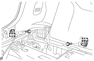
Remove the 2 bolts.
-
Disengage each guide and remove the 2 luggage hold belt striker assemblies.
-
-
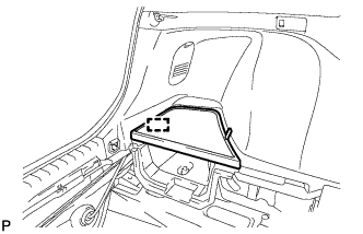
REMOVE TONNEAU COVER HOLDER CAP (for LH Side)
-
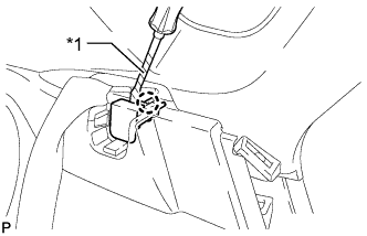
Text in Illustration *1 Protective Tape Using a screwdriver, disengage the claw and remove the tonneau cover holder cap.
Tech Tips
Tape the screwdriver tip before use.
-
-
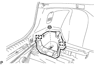
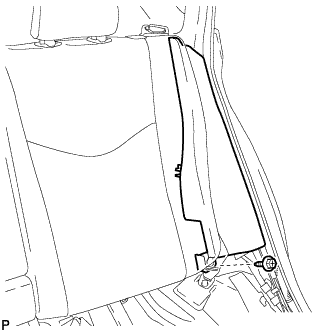
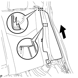
REMOVE DECK TRIM SIDE PANEL ASSEMBLY LH (for LH Side)
-
Remove the screw.
-
Disengage the 7 claws and 2 clips.
-
Disconnect the connector and remove the deck trim side panel assembly LH.
-
-
REMOVE REAR SIDE SEATBACK ASSEMBLY RH (for RH Side)
-
Remove the bolt.
-
Disengage the 2 guides and remove the rear side seatback assembly RH as shown in the illustration.
-
-
REMOVE LUGGAGE HOLD BELT STRIKER ASSEMBLY (for RH Side)
Tech Tips
Use the same procedure described for the LH side.
-
REMOVE TONNEAU COVER HOLDER CAP (for RH Side)
Tech Tips
Use the same procedure described for the LH side.
-
REMOVE DECK TRIM SIDE PANEL ASSEMBLY RH (for RH Side)
-
Remove the screw.
-
Disengage the 7 claws and 2 clips, and remove the deck trim side panel assembly RH.
-
-
REMOVE REAR WHEEL
-
SEPARATE REAR HEIGHT CONTROL SENSOR SUB-ASSEMBLY RH (w/ Height Control Sensor)
-
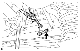
Remove the bolt and separate the rear height control sensor sub-assembly RH from the rear axle beam assembly.
-
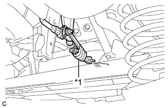
Text in Illustration *1 Vinyl Tape Using a vinyl tape, secure the rear height control sensor sub-assembly RH as shown in the illustration.
-
-
REMOVE REAR NO. 1 SHOCK ABSORBER CUSHION WASHER
-
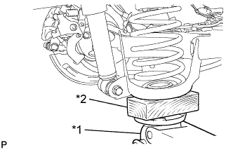
Text in Illustration *1 Jack *2 Wooden Block Support the spring seat of the rear axle beam assembly using a jack and wooden block.
CAUTION:
Do not jack up the rear axle beam assembly too high as the vehicle may fall.
Note
Keep supporting the rear axle beam assembly with a jack until the installation of the rear shock absorber assembly has been completed.
Tech Tips
Support the rear shock absorber at a position where it compresses by approximately 20 to 30 mm (0.787 to 1.18 in.).
-
Using a hexagon socket wrench, secure the rear shock absorber rod and remove the lock nut.
Note
Securely insert the hexagon socket wrench to the rear shock absorber rod to prevent damage to the rear shock absorber assembly when removing the nut.
-
Remove the rear No. 1 shock absorber cushion washer.
-
-
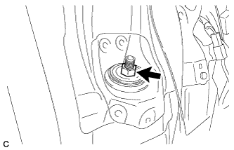
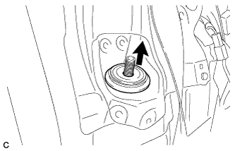
REMOVE REAR SUSPENSION SUPPORT
-
Remove the rear suspension support.
-
-
REMOVE REAR SHOCK ABSORBER ASSEMBLY
-
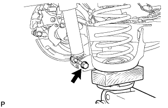
Remove the bolt while holding the nut and remove the rear shock absorber assembly.
Note
Since the stopper nut is used, turn the bolt.
-
-
REMOVE REAR NO. 1 SPRING BUMPER
-
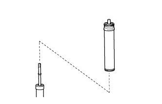
Remove the rear No. 1 spring bumper from the rear shock absorber assembly.
-