REAR AXLE HUB INSTALLATION

Tech Tips
-
Use the same procedure for the RH side and LH side.
-
The procedure listed below is for the LH side.
-
INSTALL REAR AXLE HUB AND BEARING ASSEMBLY
-
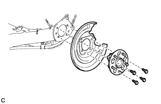
Install the rear axle hub and bearing assembly and rear disc brake dust cover to the rear axle beam assembly with the 4 bolts.
- Torque:
- 90 N*m { 918 kgf*cm, 66 ft.*lbf }
-
-
INSPECT REAR AXLE HUB BEARING LOOSENESS
-
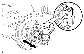
Using a dial indicator, check for looseness near the center of the axle hub.
Maximum looseness 0.05 mm (0.00196 in.) Note
-
Ensure that the dial indicator is set perpendicular to the measurement surface.
-
Keep the magnet of the dial indicator away from the rear axle hub and bearing (rear speed sensor).
Tech Tips
If the looseness exceeds the maximum, replace the rear axle hub and bearing assembly.
-
-
-
INSPECT REAR AXLE HUB RUNOUT
-
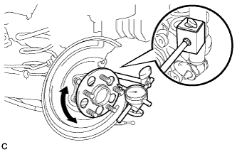
Using a dial indicator, check for runout on the surface of the axle hub outside the rear axle hub bolt.
Maximum runout 0.05 mm (0.00196 in.) Note
-
Ensure that the dial indicator is set perpendicular to the measurement surface.
-
Make sure to install the tip of the dial indicator towards the outside of the rear axle hub bolt.
-
Keep the magnet of the dial indicator away from the rear axle hub and bearing (rear speed sensor).
Tech Tips
If the runout exceeds the maximum, replace the rear axle hub and bearing assembly.
-
-
-
INSTALL REAR DISC
-
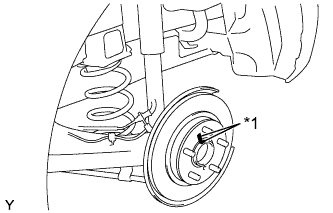
Text in Illustration *1 Matchmark Align the matchmarks of the disc and axle hub, and install the disc.
Note
When replacing the disc with a new one, select the installation position where the rear disc has minimal runout.
-
-
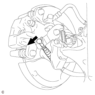
INSTALL REAR DISC BRAKE CALIPER ASSEMBLY
-
Install the rear disc brake caliper assembly with the 2 bolts.
- Torque:
- 57 N*m { 585 kgf*cm, 42 ft.*lbf }
-
-
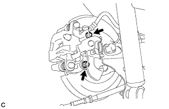
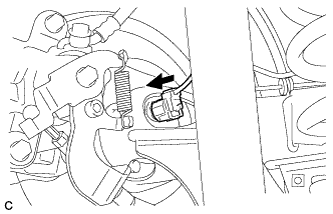
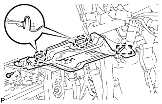
CONNECT NO. 3 PARKING BRAKE CABLE ASSEMBLY
-
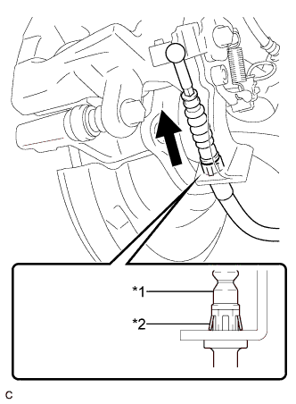
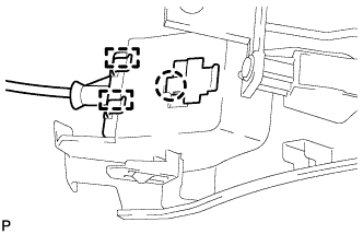
Text in Illustration *1 No. 3 Parking Brake Cable Assembly *2 Clip Install the No. 3 parking brake cable assembly to the rear disc brake cylinder assembly.
Tech Tips
Be sure to engage the No. 3 parking brake cable assembly clip onto the rear disc brake cylinder assembly as shown in the illustration.
-
Connect the No. 3 parking brake cable assembly to the rear disc brake cylinder assembly.
-
-
CONNECT REAR SPEED SENSOR WIRE
-
Connect the rear speed sensor wire connector to the rear speed sensor.
-
-
ADJUST PARKING BRAKE
Tech Tips
-
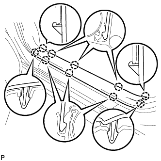
INSTALL LOWER INSTRUMENT PANEL FINISH PANEL ASSEMBLY (for LHD)
-
Connect each connector.
-
Engage the clamp.
-
Engage the 2 guides and claw to connect the hood lock control cable.
-
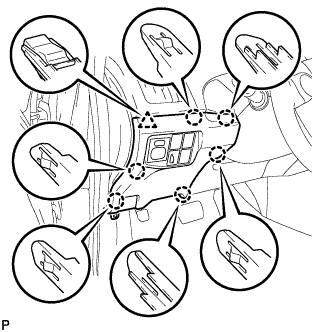
Engage the 6 claws and clip.
-
Install the lower instrument panel finish panel assembly with the screw <C>.
-
-
INSTALL COWL SIDE TRIM SUB-ASSEMBLY LH (for LHD)
-
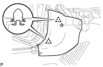
Engage the 2 clips.
-
Install the cowl side trim board LH with the clip.
-
-
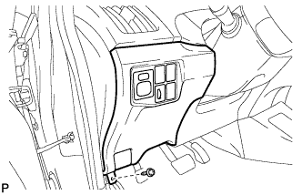
INSTALL FRONT DOOR SCUFF PLATE LH (for LHD)
-
Engage the 10 claws to install the front door scuff plate LH.
-
-
INSTALL NO. 1 INSTRUMENT PANEL UNDER COVER SUB-ASSEMBLY (for RHD)
-
Connect each connector.
-
Engage the guide and 2 claws.
-
Install the No. 1 instrument panel under cover sub-assembly with the screw <D>.
-
-
INSTALL REAR WHEEL
- Torque:
- 103 N*m { 1050 kgf*cm, 76 ft.*lbf }
-
CONNECT CABLE TO NEGATIVE BATTERY TERMINAL
-
Connect the cable to the negative (-) battery terminal.
Note
When disconnecting the cable, some systems need to be initialized after the cable is reconnected Click here.
-
Connect the reservoir level switch connector.
-
Clear the DTCs Click here.
-
-
INSTALL REAR NO. 3 FLOOR BOARD
-

Engage the 2 guides to install the rear No. 3 floor board.
-
-
INSTALL REAR DECK FLOOR BOX
-
Install the rear deck floor box.
-
-
INSTALL REAR NO. 2 FLOOR BOARD
-

Engage the 3 guides <A>.
-
Engage the 2 guides <B> and install the rear No. 2 floor board as shown in the illustration.
-
-
CHECK FOR SPEED SENSOR SIGNAL
Tech Tips