TCM REMOVAL

-
PRECAUTION (w/ Navigation System for HDD)
Note
After the power switch is turned off, the display and navigation module display (HDD navigation system) records various types of memory and settings. As a result, after turning the power switch off, make sure to wait at least 60 seconds before disconnecting the cable from the negative (-) battery terminal.
-
REMOVE REAR NO. 2 FLOOR BOARD
-

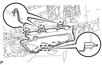
Disengage the 2 guides <A> as shown in the illustration.
-
Disengage the 3 guides <B> and remove the rear No. 2 floor board.
-
-
REMOVE REAR DECK FLOOR BOX
-
Remove the rear deck floor box.
-
-
REMOVE REAR NO. 3 FLOOR BOARD
-

Disengage the 2 guides and remove the rear No. 3 floor board.
-
-
DISCONNECT CABLE FROM NEGATIVE BATTERY TERMINAL
Note
When disconnecting the cable, some systems need to be initialized after the cable is reconnected Click here.
-
REMOVE NO. 2 INSTRUMENT PANEL UNDER COVER SUB-ASSEMBLY
-
Disengage the 3 claws and guide.
-
Disconnect each connector and remove the No. 2 instrument panel under cover sub-assembly.
-
-
REMOVE GLOVE COMPARTMENT DOOR ASSEMBLY
-
for LHD:
-
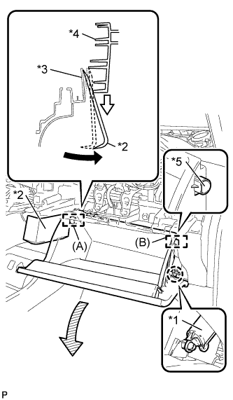
Text in Illustration *1 Glove Compartment Door Stopper Sub-assembly *2 Moulding Remover *3 Lower Instrument Panel Sub-assembly *4 Glove Compartment Door Assembly *5 Stopper Disengage the claw and release the glove compartment door stopper.
-
Insert the moulding remover into the location shown in the illustration.
-
Move the moulding remover in the direction indicated by the arrow to bend the lower instrument panel sub-assembly and release the stopper (A).
Tech Tips
Use the same procedure to release the stopper (B).
-
-
for RHD:
-
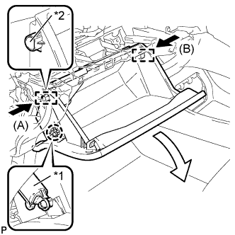
Text in Illustration *1 Glove Compartment Door Stopper Sub-assembly *2 Stopper Disengage the claw and release the glove compartment door stopper.
-
Slightly bend stoppers (A) and (B) in the directions indicated by the arrows in the illustration and pull the glove compartment door assembly until the stoppers are released.
-
-
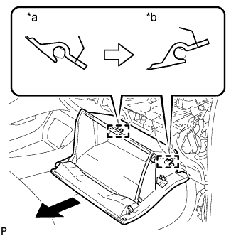
Text in Illustration *a Close *b Open Approximately Open the glove compartment door assembly to approximately 55° from its closed position. Pull it horizontally in the direction indicated by the arrow to disengage the 2 hinges and remove the glove compartment door assembly.
Note
Pulling the glove compartment door assembly upward to remove it causes the hinges to deform. Be sure to pull out the glove compartment door assembly horizontally.
-
-
REMOVE ECU INTEGRATION BOX (for LHD)
-
Disconnect each connector.
-
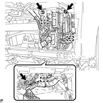
Disengage the 3 clamps and disconnect the wire harness.
-
Remove the bolt, 2 nuts and ECU integration box.
-
-
REMOVE ECU INTEGRATION BOX (for RHD)
-
Disconnect each connector.
-
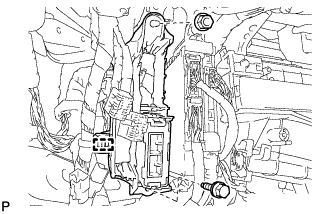
Disengage the clamp and disconnect the wire harness.
-
Remove the bolt, nut and ECU integration box.
-
-
REMOVE TRANSMISSION CONTROL ECU ASSEMBLY
-
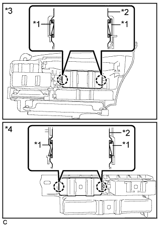
Text in Illustration *1 Claw *2 Transmission Control ECU Assembly *3 LHD *4 RHD Disengage the 2 claws and remove the transmission control ECU assembly from the ECU integration box.
-