SHIFT LEVER INSTALLATION

-
INSTALL SHIFT LOCK CONTROL UNIT ASSEMBLY
-
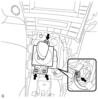
Install the shift lock control unit assembly with the 3 nuts.
- Torque:
- 12 N*m { 122 kgf*cm, 9 ft.*lbf }
-
Connect the connector to the shift lock control unit assembly.
-
-
INSTALL LOWER CENTER INSTRUMENT CLUSTER FINISH PANEL SUB-ASSEMBLY
-
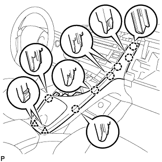
Engage the 7 claws and 2 clips to install the lower center instrument cluster finish panel sub-assembly.
-
-
INSTALL INTEGRATION CONTROL AND PANEL ASSEMBLY
-
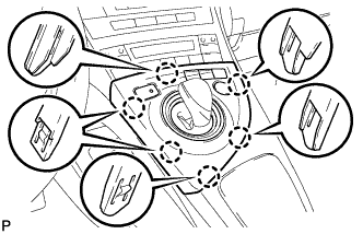
Connect each connector.
-
Engage the 6 claws to install the integration control and panel assembly.
-
-
INSTALL SHIFT LEVER KNOB
-
Using a die (M6 x P1.00 mm), clean the threads of the shift control unit assembly.
-
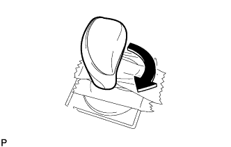
Turn the shift lever knob in the direction of the arrow in the illustration to install it.
-
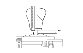
Text in Illustration *1 Measuring Point Using a vernier caliper, adjust the height of the shift lever knob.
Standard height 4.1 to 7.1 mm (0.161 to 0.280 in.) -
Remove the protective tape around the shift lock control unit assembly.
-
-
CONNECT CABLE TO NEGATIVE BATTERY TERMINAL
Note
When disconnecting the cable, some systems need to be initialized after the cable is reconnected Click here.
-
INSTALL REAR NO. 3 FLOOR BOARD
-

Engage the 2 guides to install the rear No. 3 floor board.
-
-
INSTALL REAR DECK FLOOR BOX
-
Install the rear deck floor box.
-
-
INSTALL REAR NO. 2 FLOOR BOARD
-

Engage the 3 guides <A>.
-
Engage the 2 guides <B> and install the rear No. 2 floor board as shown in the illustration.
-
-
INSPECT SHIFT LEVER
-
Turn the power switch on (READY).
-
Check that all available shift positions can be selected moving the shift lever.
Tech Tips
After the shift lever is replaced with a new one, perform the above operation. If this operation is not performed, moving the shift lever may not initially select shift positions.
-