HYBRID VEHICLE TRANSAXLE INSTALLATION

-
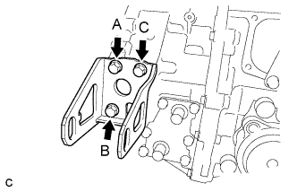
INSTALL ENGINE MOUNTING BRACKET LH
-
Install the engine mounting bracket LH with 3 new bolts in several steps.
- Torque:
- 64 N*m { 653 kgf*cm, 47 ft.*lbf }
Note
Temporarily tighten bolt A, and then fully tighten the 3 bolts in the order of B, C and A.
-
-
INSTALL REAR ENGINE MOUNTING BRACKET
-
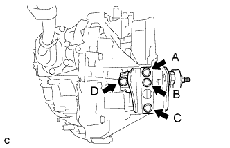
Install the rear engine mounting bracket with the 4 bolts in several steps.
- Torque:
- 45 N*m { 459 kgf*cm, 33 ft.*lbf }
Note
Temporarily tighten bolt A, and then fully tighten the 4 bolts in the order of C, B, D and A.
-
-
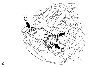
INSTALL FRONT ENGINE MOUNTING BRACKET
-
Install the front engine mounting bracket with the 3 bolts in several steps.
- Torque:
- 64 N*m { 653 kgf*cm, 47 ft.*lbf }
Note
Temporarily tighten bolt A, and then fully tighten the 3 bolts in the order of B, C and A.
-
-
INSTALL MOTOR CABLE BRACKET
-
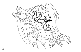
Install the motor cable bracket with the bolt.
- Torque:
- 23 N*m { 235 kgf*cm, 17 ft.*lbf }
-
-
INSTALL WIRE HARNESS CLAMP BRACKET
-
Install the 2 wire harness clamp brackets with the 2 bolts.
- Torque:
- 23 N*m { 235 kgf*cm, 17 ft.*lbf }
-
-
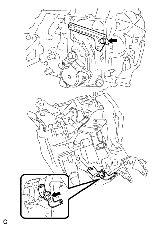
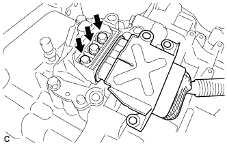
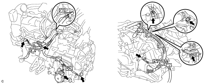
INSTALL MOTOR CABLE
Note
Wear insulated gloves.
-
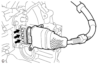
Install the motor cable to the hybrid transaxle assembly with the 3 bolts.
- Torque:
- 10 N*m { 102 kgf*cm, 7 ft.*lbf }
Note
Keep the sealing surface of the motor cable and the connector terminal joint free of foreign matter.
-
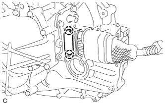
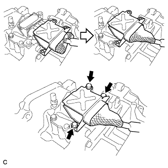
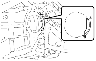
Engage the 2 claws to install a new terminal cap.
Note
When installing the terminal cap to the motor cable terminal block, keep the sealing surface free of foreign matter.
-
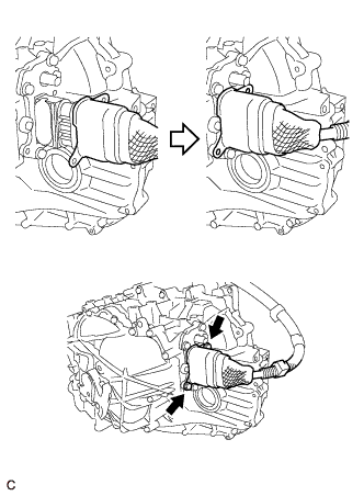
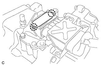
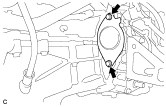
Place the motor cable connector shell in position and install it with the 2 bolts.
- Torque:
- 10 N*m { 102 kgf*cm, 7 ft.*lbf }
-
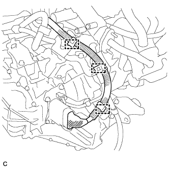
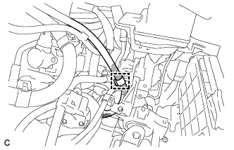
Connect the 3 clamps.
-
-
INSTALL GENERATOR CABLE
Note
Wear insulated gloves.
-
Install the generator cable to the hybrid transaxle assembly with the 3 bolts.
- Torque:
- 10 N*m { 102 kgf*cm, 7 ft.*lbf }
Note
Keep the sealing surface of the generator cable and the connector terminal joint free of foreign matter.
-
Engage the 2 claws to install a new terminal cap.
Note
When installing the terminal cap to the generator cable terminal block, keep the sealing surface free of foreign matter.
-
Place the generator cable connector shell in position and install it with the 3 bolts.
- Torque:
- 20 N*m { 204 kgf*cm, 15 ft.*lbf }
-
Connect the generator cable clamp to the motor cable bracket.
-
-
INSTALL HYBRID VEHICLE TRANSAXLE ASSEMBLY
-
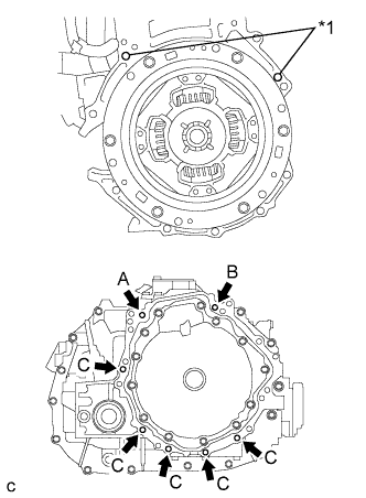
Text in Illustration *1 Knock Pin Make sure that the knock pins are installed on the engine.
-
Using an engine lifter, align the engine assembly and hybrid vehicle transaxle assembly, fit the knock pins into the knock pin holes, and tighten the 7 bolts shown in the illustration.
- Torque:
- 33 N*m { 337 kgf*cm, 24 ft.*lbf }
Note
-
Make sure to align the hybrid vehicle transaxle assembly so that the input shaft of the hybrid vehicle transaxle assembly will be inserted straight into the inner splines of the transmission input damper.
-
When inserting the input shaft of the hybrid vehicle transaxle assembly into the inner splines of the transmission input damper, do not shake the hybrid vehicle transaxle assembly excessively.
-
When mounting the hybrid vehicle transaxle assembly to the engine assembly, make sure to securely fit the knock pins into the knock holes.
-
Push in the hybrid vehicle transaxle assembly so that the contact surfaces of the engine assembly and the hybrid vehicle transaxle assembly will be are aligned evenly.
-
While mounting the hybrid vehicle transaxle assembly to the engine assembly, temporarily tighten the bolt (A), and then fully tighten the 3 bolts in the order of B, A and C.
-
Do not hang the hybrid vehicle transaxle assembly off of the engine assembly if the contact surfaces of the engine assembly and the hybrid vehicle transaxle assembly are not in full contact. The knock holes of the hybrid vehicle transaxle case may be deformed due to the excessive weight of the engine assembly and hybrid vehicle transaxle assembly, resulting in misalignment between the engine assembly and hybrid vehicle transaxle assembly.
-
-
INSTALL FLYWHEEL HOUSING SIDE COVER
-
Install the flywheel housing side cover.
-
-
INSTALL STARTER HOLE INSULATOR
-
Install the starter hole insulator with the 2 bolts.
- Torque:
- 37 N*m { 377 kgf*cm, 27 ft.*lbf }
-
-
CONNECT WIRE HARNESS
-
Connect the 12 wire harness clamps and 6 connectors and install the 2 bolts.
- Torque:
- 12 N*m { 122 kgf*cm, 9 ft.*lbf }
-
-
INSTALL RADIATOR PIPE
-
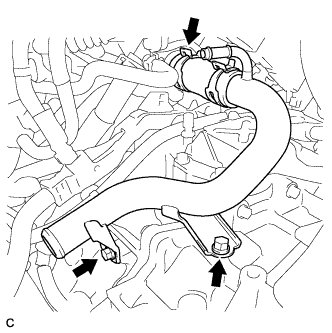
Install the radiator pipe with the 2 bolts.
- Torque:
- 19 N*m { 194 kgf*cm, 14 ft.*lbf }
-
Install the No. 3 radiator hose with the clamp.
-
-
INSTALL REAR ENGINE MOUNTING INSULATOR
-
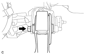
Install the rear engine mounting insulator to the engine mounting bracket with the through bolt.
- Torque:
- 95 N*m { 969 kgf*cm, 70 ft.*lbf }
Tech Tips
Perform this procedure only when replacement of the engine mounting insulator is necessary.
-
-
INSTALL FRONT ENGINE MOUNTING INSULATOR
-
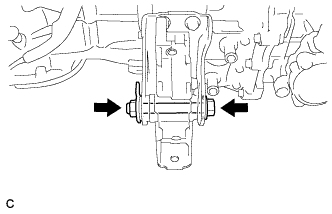
Temporarily install the front engine mounting insulator with the bolt and nut.
-
-
INSTALL ENGINE ASSEMBLY WITH TRANSAXLE
Tech Tips