ELECTRONIC SHIFT LEVER SYSTEM "P" Position Switch Indicator Light Circuit
DESCRIPTION
The indicator light comes on when the transmission shift main switch (P position switch) is pressed (park (P) selected), goes off when a shift state other than park (P) is selected and blinks or goes off when a system malfunction occurs. Then an error message is displayed on the multi display.
WIRING DIAGRAM
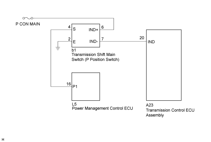
INSPECTION PROCEDURE
PROCEDURE
-
CHECK TRANSMISSION SHIFT MAIN SWITCH (INDICATOR LIGHT)
-
Turn the power switch on (IG).
-
Depress the brake pedal and move the selector lever to N.
-
Inspect the indicator light condition by operating the transmission shift main switch (P position switch).
Result Condition of Indicator Light Proceed to Indicator light does not go off. (Remains on) A Indicator light does not come on. B -
Turn the power switch off.
B 
CHECK HARNESS AND CONNECTOR (TRANSMISSION SHIFT MAIN SWITCH POWER SOURCE CIRCUIT) Click here
A 
-
-
CHECK TRANSMISSION SHIFT MAIN SWITCH (INDICATOR LIGHT)
-
Disconnect the A23 transmission control ECU assembly.
-
Turn the power switch on (IG).
-
Inspect the indicator light condition by operating the transmission shift main switch (P position switch).
Result Condition of Indicator Light Proceed to Comes on A Does not come on B Note
Turning the power switch on (IG) with the transmission control ECU assembly connector disconnected causes other DTCs to be stored. Clear the DTCs after performing this inspection.
-
Turn the power switch off.
-
Connect the transmission control ECU assembly connector.
B 
REPLACE TRANSMISSION CONTROL ECU ASSEMBLY Click here
A
-
-
CHECK HARNESS AND CONNECTOR (TRANSMISSION CONTROL ECU - TRANSMISSION SHIFT MAIN SWITCH)
-
Disconnect the A23 transmission control ECU assembly connector.
-
Disconnect the b1 transmission shift main switch (P position switch) connector.
-
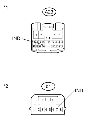
Text in Illustration *1 Front view of wire harness connector
(to Transmission Control ECU Assembly)
*2 Front view of wire harness connector
(to Transmission Shift Main Switch (P Position Switch))
Measure the resistance according to the value(s) in the table below.
Standard Resistance (Check for Short) Tester Connection Switch Condition Specified Condition A23-20 (IND) or b1-7 (IND-) - Body ground and other terminals Power switch off 10 kΩ or higher -
Connect the transmission shift main switch (P position switch) connector.
-
Connect the transmission control ECU assembly connector.
NG
REPAIR OR REPLACE HARNESS OR CONNECTOR
OK 
REPLACE TRANSMISSION SHIFT MAIN SWITCH
-
-
CHECK HARNESS AND CONNECTOR (TRANSMISSION SHIFT MAIN SWITCH POWER SOURCE CIRCUIT)
-
Disconnect the b1 transmission shift main switch (P position switch) connector.
-
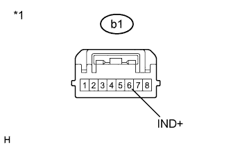
Text in Illustration *1 Front view of wire harness connector
(to Transmission Shift Main Switch (P Position Switch))
Measure the voltage according to the value(s) in the table below.
Standard Voltage Tester Connection Switch Condition Specified Condition b1-6 (IND+) - Body ground Power switch off 9 to 14 V -
Connect the transmission shift main switch (P position switch) connector.
NG
CHECK AND REPAIR POWER SOURCE CIRCUIT
OK
-
-
INSPECT TRANSMISSION SHIFT MAIN SWITCH
-
Disconnect the b1 transmission shift main switch (P position switch) connector.
-
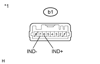
Text in Illustration *1 Component without harness connected
(Transmission Shift Main Switch (P Position Switch))
Apply auxiliary battery voltage between terminals b1-6 (IND+) and b1-7 (IND-) and check the indicator light.
Result Condition Specified Condition Auxiliary battery voltage applied between terminals b1-6 (IND+) and b1-7 (IND-) Comes on Tech Tips
Terminals No. 1 and No. 8 on the component side connector are empty.
-
Connect the transmission shift main switch (P position switch) connector.
NG
REPLACE TRANSMISSION SHIFT MAIN SWITCH
OK
-
-
CHECK HARNESS AND CONNECTOR (TRANSMISSION CONTROL ECU - TRANSMISSION SHIFT MAIN SWITCH)
-
Disconnect the A23 transmission control ECU assembly connector.
-
Disconnect the b1 transmission shift main switch (P position switch) connector.
-
Text in Illustration *1 Front view of wire harness connector
(to Transmission Control ECU Assembly)
*2 Front view of wire harness connector
(to Transmission Shift Main Switch (P Position Switch))
Measure the resistance according to the value(s) in the table below.
Standard Resistance (Check for Open) Tester Connection Switch Condition Specified Condition A23-20 (IND) - b1-7 (IND-) Power switch off Below 1 Ω -
Connect the transmission shift main switch (P position switch) connector.
-
Connect the transmission control ECU assembly connector.
NG
REPAIR OR REPLACE HARNESS OR CONNECTOR
OK
REPLACE TRANSMISSION CONTROL ECU ASSEMBLY Click here
-