ELECTRONIC SHIFT LEVER SYSTEM, Diagnostic DTC:C2315

| DTC Code | DTC Name |
|---|---|
| C2315 | HV System |
DESCRIPTION
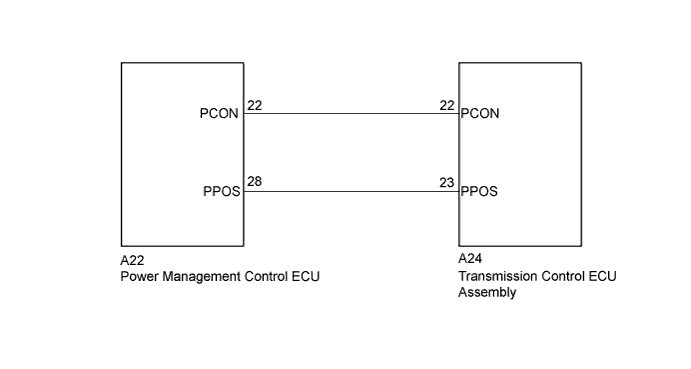
The transmission control ECU receives a P position switch signal from the power management control ECU (HV CPU) and activates the parking lock motor by controlling current, causing the parking lock mechanism to switch. When the power management control ECU (HV CPU) detects a malfunction with the P position switch or P position signal, it sends an information signal to the transmission control ECU. After receiving this signal, the transmission control ECU outputs this DTC.
| DTC No. | DTC Detection Condition | Trouble Area |
|---|---|---|
| C2315 | With the power switch on (IG) (IG circuit malfunction is not detected), a malfunction signal is received from the power management control ECU for 2 second or more. | Power management control ECU |
WIRING DIAGRAM
INSPECTION PROCEDURE
PROCEDURE
-
CHECK DTC OUTPUT (HV)
-
Connect the intelligent tester to the DLC3.
-
Turn the power switch on (IG).
-
Enter the following menus: Powertrain / Hybrid Control / Trouble Codes.
-
Check if DTCs are output.
Result Result Proceed to Any of the following DTCs are not output. A Any of the following DTCs are output. B DTC No. Relevant Diagnosis P0851-579 Park/Neutral Switch Input Circuit Low P0852-580 Park/Neutral Switch Input Circuit High P085D-599 Gear Shift Control Module "A" Performance P0861-597 Gear Shift Control Module "A" Communication Circuit Low P0862-598 Gear Shift Control Module "A" Communication Circuit High U1107-436 Lost Communication with Power Management Module -
Turn the power switch off.
B 
GO TO DTC CHART Click here
A 
-
-
CLEAR DTC
-
Connect the intelligent tester to the DLC3.
-
Turn the power switch on (IG).
-
Enter the following menus: Chassis / Transmission Control / Trouble Codes.
-
Read and record the DTCs and freeze frame data.
-
Clear DTCs and freeze frame data.
-
Turn the power switch off.
NEXT
-
-
CHECK DTC OUTPUT (ALL)
-
Connect the intelligent tester to the DLC3.
-
Turn the power switch on (IG).
-
Wait for 2 seconds or more.
-
Check for DTCs of all systems by following the prompts on the intelligent tester screen.
-
Check if DTCs are output.
Result Result Proceed to DTC is not output. A C2315 only is output. B C2315 and other DTCs are output together. C Tech Tips
DTC C2315 only may be output when the P position switch (transmission shift main switch) connector is disconnected and reconnected.
-
Turn the power switch off.
B
REPLACE POWER MANAGEMENT CONTROL ECU Click here
C
GO TO DTC CHART
A 
END
-