ELECTRONIC SHIFT LEVER SYSTEM, Diagnostic DTC:C2309

| DTC Code | DTC Name |
|---|---|
| C2309 | Open in B+ Circuit |
DESCRIPTION
Battery voltage will be applied to the +B terminal when the power switch is turned on (IG). When a +B terminal voltage malfunction is detected, the transmission control ECU outputs this DTC.
| DTC No. | DTC Detection Condition | Trouble Area |
|---|---|---|
| C2309 | With the power switch on (IG), voltage of transmission control ECU terminal +B is 3 V or less for 1 second or more. |
|
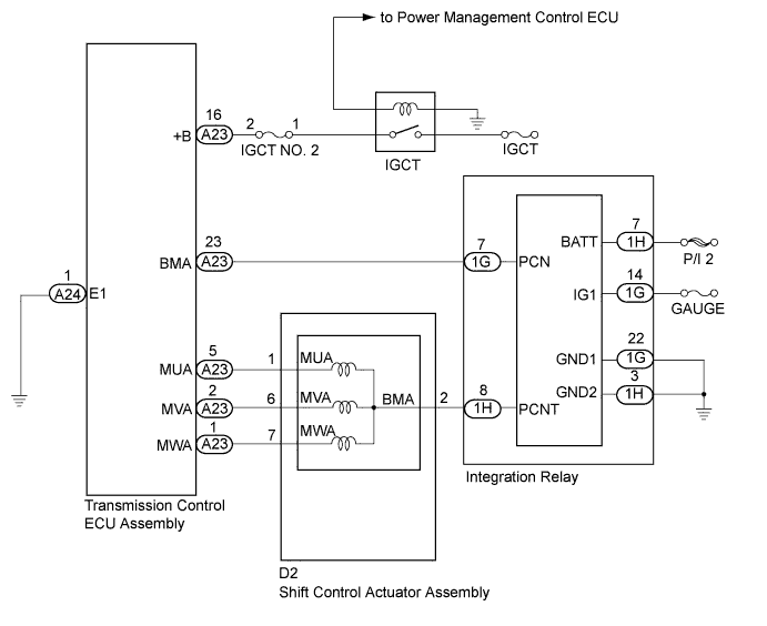
WIRING DIAGRAM
INSPECTION PROCEDURE
Note
It is not possible to clear the following DTCs using the intelligent tester: DTCs C2300 (Actuator System Malfunction), C2301 (Shift Changing Time Malfunction), C2303 (Short in Power Source Relay Circuit), C2304 (Open or Short Circuit in U Phase), C2305 (Open or Short Circuit in V Phase), C2306 (Open or Short Circuit in W Phase), C2307 (Power Supply) and C2309 (Open in B+ Circuit). After the repair, it is necessary to disconnect the P CON MAIN fuse and wait for at least 60 seconds to clear the DTCs.
PROCEDURE
-
READ VALUE USING INTELLIGENT TESTER (IG(+B) VOLTAGE VALUE)
-
Connect the intelligent tester to the DLC3.
-
Turn the power switch on (IG).
-
Enter the following menus: Chassis / Transmission Control / Data List / IG(+B) Voltage Value.
-
Read the Data List displayed on the intelligent tester.
Result Result Proceed to 3 V or less A Other than above B -
Turn the power switch off.
B 
REPLACE TRANSMISSION CONTROL ECU ASSEMBLY Click here
A 
-
-
READ VALUE USING INTELLIGENT TESTER (BATTERY VOLTAGE VALUE)
-
Connect the intelligent tester to the DLC3.
-
Turn the power switch on (IG).
-
Enter the following menus: Chassis / Transmission Control / Data List / Battery Voltage Value.
-
Read the Data List displayed on the intelligent tester.
Result Result Proceed to 9 V or more A Other than above B -
Turn the power switch off.
B
CHARGE OR REPLACE AUXILIARY BATTERY Click here
A
-
-
CHECK HARNESS AND CONNECTOR (TRANSMISSION CONTROL ECU ASSEMBLY - IGCT NO. 2 FUSE)
-
Disconnect the A23 transmission control ECU assembly connector.
-
Remove the IGCT No. 2 fuse from the engine room junction block assembly.
-
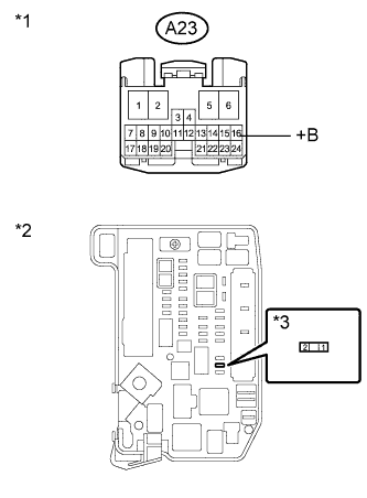
Text in Illustration *1 Front view of wire harness connector
(to Transmission Control ECU Assembly)
*2 Engine Room Junction Block Assembly *3 IGCT No. 2 fuse Measure the resistance according to the value(s) in the table below.
Standard resistance (Check for Open) Tester Connection Switch Condition Specified Condition A23-16 (+B) - 2 (IGCT No. 2 fuse) Power switch off Below 1 Ω Standard resistance (Check for Short) Tester Connection Switch Condition Specified Condition A23-16 (+B) - Body ground and other terminals Power switch off 10 kΩ or higher Note
Be careful not to break the fuse holder by forcing the tester probes into it during this inspection.
-
Install the IGCT No. 2 fuse.
-
Connect the transmission control ECU assembly connector.
NG
REPAIR OR REPLACE HARNESS OR CONNECTOR
OK 
CHECK AND REPAIR POWER SOURCE CIRCUIT
-