ELECTRONIC SHIFT LEVER SYSTEM, Diagnostic DTC:C2304, C2305, C2306

| DTC Code | DTC Name |
|---|---|
| C2304 | Open or Short Circuit in U Phase |
| C2305 | Open or Short Circuit in V Phase |
| C2306 | Open or Short Circuit in W Phase |
DESCRIPTION
The shift control actuator consists of the parking lock motor and the rotation angle sensor. The transmission control ECU receives a P position switch signal from the power management control ECU (HV CPU) and activates the parking lock motor by controlling current, causing the parking lock mechanism to switch. The transmission control ECU outputs these DTCs when it detects a malfunction in the parking lock motor system.
| DTC No. | DTC Detection Condition | Trouble Area |
|---|---|---|
| C2304 | With the power switch on (IG) (battery voltage is 8 V or more), voltage of transmission control ECU terminal MUA is 6 V or less for 1 second or more. |
|
| C2305 | With the power switch on (IG) (battery voltage is 8 V or more), voltage of transmission control ECU terminal MVA is 6 V or less for 1 second or more. | |
| C2306 | With the power switch on (IG) (battery voltage is 8 V or more), voltage of transmission control ECU terminal MWA is 6 V or less for 1 second or more. |
WIRING DIAGRAM
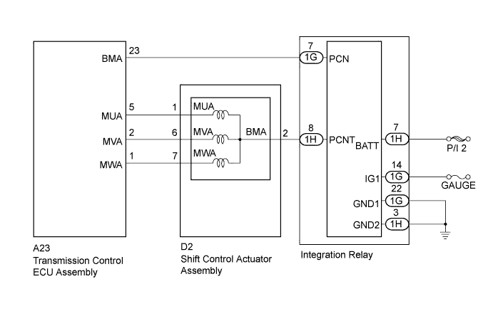
INSPECTION PROCEDURE
Note
-
Do not remove/install the auxiliary battery or disconnect the cable from the battery terminal before instructed.
-
Do not disconnect the connectors before instructed.
-
It is not possible to clear the following DTCs using the intelligent tester: DTCs C2300 (Actuator System Malfunction), C2301 (Shift Changing Time Malfunction), C2303 (Short in Power Source Relay Circuit), C2304 (Open or Short Circuit in U Phase), C2305 (Open or Short Circuit in V Phase), C2306 (Open or Short Circuit in W Phase), C2307 (Power Supply) and C2309 (Open in B+ Circuit). After the repair, it is necessary to disconnect the P CON MAIN fuse and wait for at least 60 seconds to clear the DTCs.
PROCEDURE
-
CHECK DTC OUTPUT (TRANSMISSION CONTROL)
-
Connect the intelligent tester to the DLC3.
-
Turn the power switch on (IG).
-
Enter the following menus: Chassis / Transmission Control / Trouble Codes.
-
Check if DTCs are output.
Result Result Proceed to C2304, C2305 and C2306 are detected simultaneously A One of C2304, C2305 and C2306 is detected B Tech Tips
-
If DTCs C2304, 2305 and 2306 are stored at the same time, there may be a malfunction in the parking lock motor (BMA signal) power source circuit.
-
If DTC C2304, 2305 or 2306 is stored individually, there may be a malfunction in the parking lock motor (MUA, MVA or MWA signal) circuits.
-
-
Turn the power switch off.
B 
READ VALUE USING INTELLIGENT TESTER (U, V, W VOLTAGE) Click here
A 
-
-
CHECK FREEZE FRAME DATA
-
Connect the intelligent tester to the DLC3.
-
Turn the power switch on (IG).
-
Enter the following menus: Chassis / Transmission Control / Trouble Codes.
-
Read the freeze frame data of C2304, 2305 and 2306.
Result Result Proceed to IG (+B) voltage is 9 V or more A IG (+B) voltage is less than 9 V B -
Turn the power switch off.
B 
REPLACE AUXILIARY BATTERY
A
-
-
CHECK NO.1 INTEGRATION RELAY
-
Turn the power switch on (IG).
-
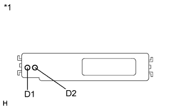
Text in Illustration *1 Component with harness connected
(Integration Relay)
Measure the voltage according to the value(s) in the table below.
Standard Voltage Tester Connection Switch Condition Specified Condition D1 - Body ground Power switch on (IG) 3.5 to 5.0 V D2 - Body ground Power switch on (IG) 3.5 to 5.0 V Tech Tips
If the result is not as specified, one of the electrical loads connected to the integration relay may have a short circuit.
Result Result Proceed to The voltage of D1 and D2 is within the specified range. A The voltage of D1 or D2 is 0.5 V or less. B -
Turn the power switch off.
B
READ VALUE USING INTELLIGENT TESTER (U, V, W VOLTAGE) Click here
A
-
-
CLEAR DTC
-
Turn the power switch on (IG).
-
Enter the following menus: Chassis / Transmission Control / Trouble Codes.
-
Read and record the DTCs and freeze frame data.
-
Turn the power switch off.
-
Disconnect the P CON MAIN fuse and wait for at least 60 seconds.
-
Check for DTCs again to see if the DTCs are cleared.
NEXT
-
-
CHARGE AUXILIARY BATTERY
-
Charge the auxiliary battery.
NEXT
-
-
CHECK DTC OUTPUT (SIMULATION TEST)
-
Connect the intelligent tester to the DLC3.
-
Release the brake pedal and turn the power switch on (IG).
Tech Tips
Do not turn the power switch on (READY).
-
Depress the brake pedal and move the selector lever to N.
-
Enter the following menus: Chassis / Transmission Control / Trouble Codes.
-
Check if DTCs are output.
Result Result Proceed to C2304, 2305 or 2306 is output A DTC is not output. B -
Turn the power switch off.
B
END (AUXILIARY BATTERY WAS INSUFFICIENTLY CHARGED)
A
-
-
READ VALUE USING INTELLIGENT TESTER (U, V, W VOLTAGE)
-
Connect the intelligent tester to the DLC3.
-
Turn the power switch on (IG).
-
Enter the following menus: Chassis / Transmission Control / Data List / U Phase Voltage Value, V Phase Voltage Value, W Phase Voltage Value.
-
Read the Data List displayed on the intelligent tester.
Result Tester Display Switch Condition Specified Condition U Phase Voltage Value Power switch on (IG) 9 to 14 V V Phase Voltage Value Power switch on (IG) 9 to 14 V W Phase Voltage Value Power switch on (IG) 9 to 14 V -
Turn the power switch off.
NG
CHECK HARNESS AND CONNECTOR (TRANSMISSION CONTROL ECU ASSEMBLY - SHIFT CONTROL ACTUATOR) Click here
OK 
REPLACE TRANSMISSION CONTROL ECU ASSEMBLY Click here
-
-
CHECK HARNESS AND CONNECTOR (TRANSMISSION CONTROL ECU ASSEMBLY - SHIFT CONTROL ACTUATOR)
-
Disconnect the A23 transmission control ECU assembly connector.
-
Disconnect the D2 shift control actuator assembly connector.
-
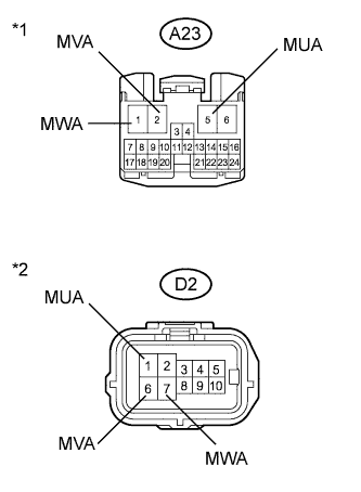
Text in Illustration *1 Front view of wire harness connector
(to Transmission Control ECU Assembly)
*2 Front view of wire harness connector
(to Shift Control Actuator Assembly)
Measure the resistance according to the value(s) in the table below.
Standard Resistance (Check for Open) Tester Connection Switch Condition Specified Condition A23-5 (MUA) - D2-1 (MUA) Power switch off Below 1 Ω A23-2 (MVA) - D2-6 (MVA) Power switch off Below 1 Ω A23-1 (MWA) - D2-7 (MWA) Power switch off Below 1 Ω Standard Resistance (Check for Short) Tester Connection Switch Condition Specified Condition A23-5 (MUA) or D2-1 (MUA) - Body ground and other terminals Power switch off 10 kΩ or higher A23-2 (MVA) or D2-6 (MVA) - Body ground and other terminals Power switch off 10 kΩ or higher A23-1 (MWA) or D2-7 (MWA) - Body ground and other terminals Power switch off 10 kΩ or higher -
Connect the shift control actuator assembly connector.
-
Connect the transmission control ECU assembly connector.
NG
REPAIR OR REPLACE HARNESS OR CONNECTOR
OK
-
-
CHECK HARNESS AND CONNECTOR (INTEGRATION RELAY POWER SOURCE CIRCUIT)
-
Disconnect the 1G and 1H integration relay connectors.
-
Turn the power switch on (IG)
-
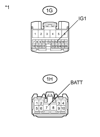
Text in Illustration *1 Front view of wire harness connector
(to Integration Relay)
Measure the voltage according to the value(s) in the table below.
Standard Voltage Tester Connection Switch Condition Specified Condition 1H-7 (BATT) - Body ground Always 9 to 14 V 1G-14 (IG1) - Body ground Power switch on (IG) 9 to 14 V -
Turn the power switch off.
-
Connect the integration relay connectors.
NG
CHECK AND REPAIR POWER SOURCE CIRCUIT
OK
-
-
CHECK HARNESS AND CONNECTOR (SHIFT CONTROL ACTUATOR ASSEMBLY - INTEGRATION RELAY)
-
Disconnect the D2 shift control actuator assembly connector.
-
Disconnect the 1H integration relay connector.
-
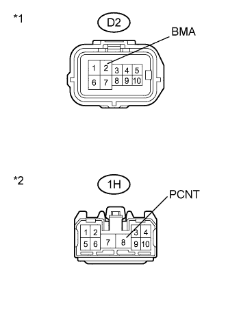
Text in Illustration *1 Front view of wire harness connector
(to Shift Control Actuator Assembly)
*2 Front view of wire harness connector
(to Integration Relay)
Measure the resistance according to the value(s) in the table below.
Standard Resistance (Check for Open) Tester Connection Switch Condition Specified Condition D2-2 (BMA) - 1H-8 (PCNT) Power switch off Below 1 Ω Standard Resistance (Check for Short) Tester Connection Switch Condition Specified Condition D2-2 (BMA) or 1H-8 (PCNT) - Body ground and other terminals Power switch off 10 kΩ or higher -
Connect the integration relay connector.
-
Connect the shift control actuator assembly connector.
NG
REPAIR OR REPLACE HARNESS OR CONNECTOR
OK
-
-
CHECK SHIFT CONTROL ACTUATOR ASSEMBLY
-
Disconnect the A23 transmission control ECU assembly connector.
-
Disconnect the 1H integration relay connector.
-
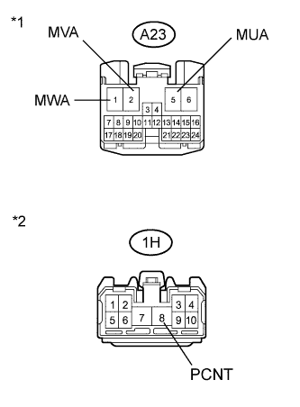
Text in Illustration *1 Front view of wire harness connector
(to Transmission Control ECU Assembly)
*2 Front view of wire harness connector
(to Integration Relay)
Measure the resistance according to the value(s) in the table below.
Standard Resistance (Check for Open) Tester Connection Switch Condition Specified Condition A23-5 (MUA) - 1H-8 (PCNT) Power switch off Below 50 Ω A23-2 (MVA) - 1H-8 (PCNT) Power switch off Below 50 Ω A23-1 (MWA) - 1H-8 (PCNT) Power switch off Below 50 Ω Standard Resistance (Check for Short) Tester Connection Switch Condition Specified Condition A23-5 (MUA) - Body ground Power switch off 10 kΩ or higher A23-2 (MVA) - Body ground Power switch off 10 kΩ or higher A23-1 (MWA) - Body ground Power switch off 10 kΩ or higher 1H-8 (PCNT) - Body ground Power switch off 10 kΩ or higher -
Connect the integration relay connector.
-
Connect the transmission control ECU assembly connector.
NG
REPLACE SHIFT CONTROL ACTUATOR ASSEMBLY Click here
OK
-
-
CHECK HARNESS AND CONNECTOR (TRANSMISSION CONTROL ECU ASSEMBLY - INTEGRATION RELAY)
-
Disconnect the A23 transmission control ECU assembly connector.
-
Disconnect the 1G integration relay connector.
-
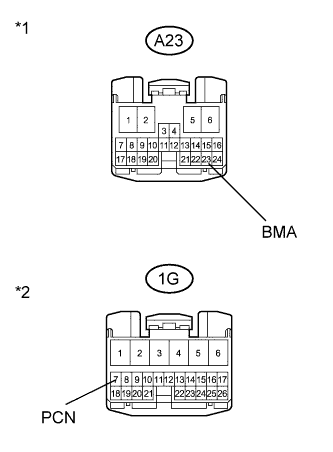
Text in Illustration *1 Front view of wire harness connector
(to Transmission Control ECU Assembly)
*2 Front view of wire harness connector
(to Integration Relay)
Measure the resistance according to the value(s) in the table below.
Standard Resistance (Check for Open) Tester Connection Switch Condition Specified Condition A23-23 (BMA) - 1G-7 (PCN) Power switch off Below 1 Ω Standard Resistance (Check for Short) Tester Connection Switch Condition Specified Condition A23-23 (BMA) or 1G-7 (PCN) - Body ground and other terminals Power switch off 10 kΩ or higher -
Connect the integration relay connector.
-
Connect the transmission control ECU assembly connector.
NG
REPAIR OR REPLACE HARNESS OR CONNECTOR
OK
-
-
CHECK HARNESS AND CONNECTOR (INTEGRATION RELAY - BODY GROUND)
-
Disconnect the 1G and 1H integration relay connectors.
-
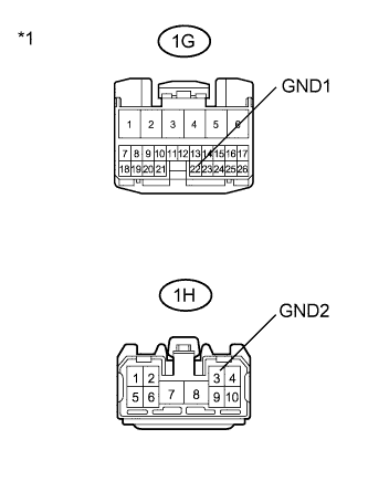
Text in Illustration *1 Front view of wire harness connector
(to Integration Relay)
Measure the resistance according to the value(s) in the table below.
Standard Resistance (Check for Open) Tester Connection Switch Condition Specified Condition 1G-22 (GND1) - Body ground Power switch off Below 1 Ω 1H-3 (GND2) - Body ground Power switch off Below 1 Ω -
Connect the integration relay connectors.
NG
REPAIR OR REPLACE HARNESS OR CONNECTOR
OK
-
-
REPLACE NO.1 INTEGRATION RELAY
-
Replace the integration relay Click here.
NEXT
REPLACE TRANSMISSION CONTROL ECU ASSEMBLY Click here
-