DYNAMIC RADAR CRUISE CONTROL SYSTEM ECU Power Source Circuit
DESCRIPTION
-
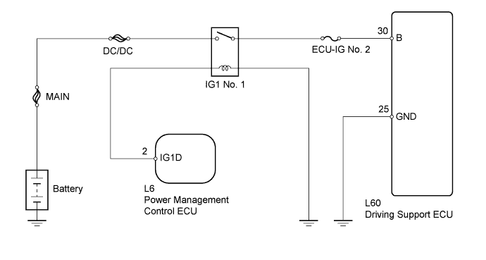
The driving support ECU assembly controls the cruise control system based on information sent from switches, sensors and ECUs.
-
The power management control ECU sends current points in the relay so that power is supplied to the driving support ECU B terminal.
WIRING DIAGRAM
INSPECTION PROCEDURE
Note
Inspect the fuses for circuits related to this system before performing the following inspection procedure.
PROCEDURE
-
CHECK DRIVING SUPPORT ECU (B VOLTAGE)
-
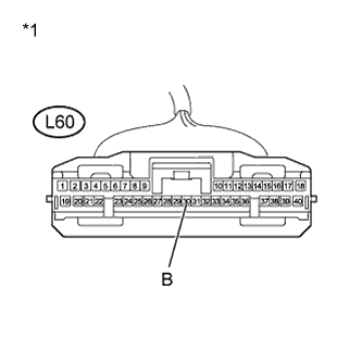
Text in Illustration *1 Front view of wire harness connector
(to Driving Support ECU)
Disconnect the driving support ECU connector.
-
Turn the power switch on (IG).
-
Measure the voltage according to the value(s) in the table below.
Standard Voltage Tester Connection Switch Condition Specified Condition L60-30 (B) - Body ground Power switch on (IG) 11 to 14 V -
Reconnect the driving support ECU connector.
NG 
INSPECT INSTRUMENT PANEL JUNCTION BLOCK ASSEMBLY Click here
OK 
-
-
CHECK HARNESS AND CONNECTOR (DRIVING SUPPORT ECU - BODY GROUND)
-
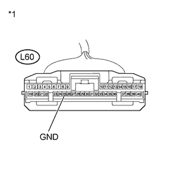
Text in Illustration *1 Front view of wire harness connector
(to Driving Support ECU)
Disconnect the driving support ECU connector.
-
Measure the resistance according to the value(s) in the table below.
Standard Resistance (Check for Open) Tester Connection Condition Specified Condition L60-25 (GND) - Body ground Always Below 1 Ω -
Reconnect the driving support ECU connector.
NG 
REPAIR OR REPLACE HARNESS OR CONNECTOR (DRIVING SUPPORT ECU - BODY GROUND)
OK 
PROCEED TO NEXT SUSPECTED AREA SHOWN IN PROBLEM SYMPTOMS TABLE Click here
-
-
INSPECT INSTRUMENT PANEL JUNCTION BLOCK ASSEMBLY
-
Remove the instrument panel junction block assembly.

-
Measure the resistance according to the value(s) in the table below.
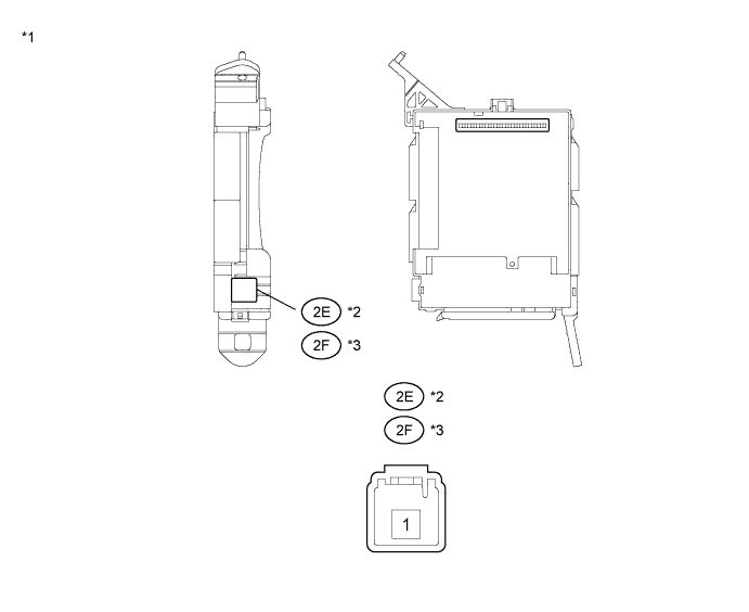
Standard Resistance for LHD Tester Connection Condition Specified Condition 2E-1 - 2B-16 Always 10 kΩ or higher 2E-1 - 2B-16 Battery voltage applied between terminals 2B-25 and 2B-6 Below 1 Ω for RHD Tester Connection Condition Specified Condition 2F-1 - 2B-16 Always 10 kΩ or higher 2F-1 - 2B-16 When battery voltage applied to terminals 2B-25 and 2B-6 Below 1 Ω Text in Illustration *1 Instrument Panel Junction Block Assembly *2 for LHD *3 for RHD - - -
Reinstall the instrument panel junction block assembly.
NG
REPLACE INSTRUMENT PANEL JUNCTION BLOCK ASSEMBLY
OK
-
-
CHECK HARNESS AND CONNECTOR (DRIVING SUPPORT ECU - INSTRUMENT PANEL JUNCTION BLOCK)
-
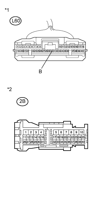
Text in Illustration *1 Front view of wire harness connector
(to Driving Support ECU)
*2 Instrument Panel Junction Block Disconnect the driving support ECU connector.
-
Disconnect the instrument panel junction block assembly connector.
-
Measure the resistance according to the value(s) in the table below.
Standard Resistance Tester Connection Condition Specified Condition L60-30 (B) - 2B-16 Always Below 1 Ω -
Reconnect the instrument panel junction block assembly connector.
-
Reconnect the driving support ECU connector.
NG
REPAIR OR REPLACE HARNESS OR CONNECTOR (DRIVING SUPPORT ECU - INSTRUMENT PANEL JUNCTION BLOCK)
OK
-
-
CHECK HARNESS AND CONNECTOR (INSTRUMENT PANEL JUNCTION BLOCK POWER SOURCE CIRCUIT)
-
Disconnect the instrument panel junction block assembly connector.
-
Measure the voltage according to the value(s) in the table below.
Standard Voltage for LHD Tester Connection Switch Condition Specified Condition 2E-1 - Body ground Always 11 to 14 V for RHD Tester Connection Switch Condition Specified Condition 2F-1 - Body ground Always 11 to 14 V Text in Illustration *1 Instrument Panel Junction Block Assembly *2 for LHD *3 for RHD - - -
Reconnect the instrument panel junction block assembly connector.
NG
REPAIR OR REPLACE HARNESS OR CONNECTOR (INSTRUMENT PANEL JUNCTION BLOCK ASSEMBLY - BATTERY)
OK
-
-
CHECK HARNESS AND CONNECTOR (INSTRUMENT PANEL JUNCTION BLOCK ASSEMBLY - BODY GROUND)
-
Text in Illustration *1 Instrument Panel Junction Block Assembly Disconnect the instrument panel junction block assembly connector.
-
Measure the resistance according to the value(s) in the table below.
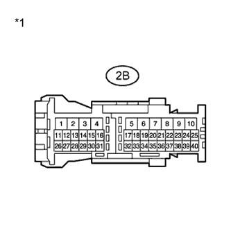
Standard Resistance Tester Connection Condition Specified Condition 2B-6 - Body ground Always Below 1 Ω -
Reconnect the instrument panel junction block assembly connector.
NG
REPAIR OR REPLACE HARNESS OR CONNECTOR (INSTRUMENT PANEL JUNCTION BLOCK ASSEMBLY - BODY GROUND)
OK
-
-
CHECK HARNESS AND CONNECTOR (POWER MANAGEMENT CONTROL ECU - INSTRUMENT PANEL J/B ASSEMBLY)
-
Disconnect the power management control ECU connector.
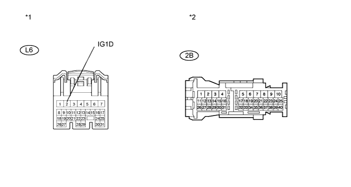
Text in Illustration *1 Front view of wire harness connector
(to Power Management Control ECU)
*2 Instrument Panel Junction Block Assembly -
Disconnect the instrument panel junction block assembly connector.
-
Measure the resistance according to the value(s) in the table below.
Standard Resistance (Check for Open) Tester Connection Condition Specified Condition 2B-25 - L6-2 (IG1D) Always Below 1 Ω Standard Resistance (Check for Short) Tester Connection Condition Specified Condition 2B-25 or L6-2 (IG1D) - Body ground Always 10 kΩ or higher -
Reconnect the power management control ECU connector.
-
Reconnect the instrument panel junction block assembly connector.
NG
REPAIR OR REPLACE HARNESS OR CONNECTOR (POWER MANAGEMENT CONTROL ECU - INSTRUMENT PANEL J/B ASSEMBLY)
OK
GO TO ENTRY AND START SYSTEM Click here
-