DYNAMIC RADAR CRUISE CONTROL SYSTEM Distance Control Switch Circuit
DESCRIPTION
The distance control switch sets the vehicle-to-vehicle distance control mode. The distance control switch is installed in the steering pad switch assembly*1 or steering pad switch RH*2. The vehicle-to-vehicle distance set value can be changed by operating the steering pad switch assembly (distance control switch)*1 or steering pad switch RH (distance control switch)*2 while the dynamic radar cruise control system is operating.
-
*1: Before October, 2010
-
*2: From October, 2010
WIRING DIAGRAM
-
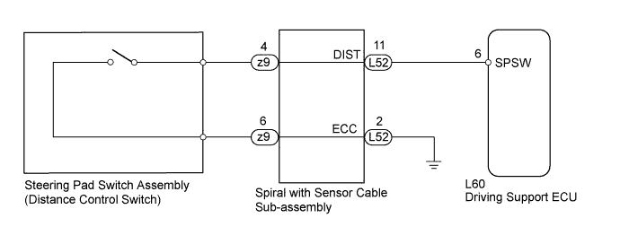
Before October, 2010
-
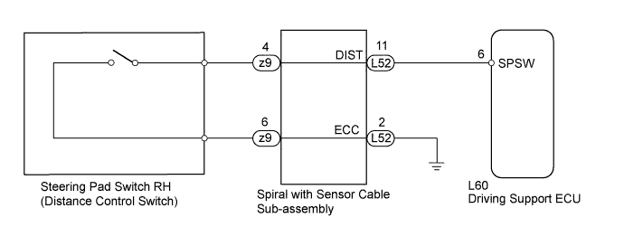
From October, 2010
INSPECTION PROCEDURE
PROCEDURE
-
READ VALUE USING INTELLIGENT TESTER (DISTANCE CONTROL SWITCH)
-
Connect the intelligent tester to the DLC3.
-
Turn the power switch on (IG).
-
Turn the intelligent tester on.
-
Enter the following menus: Powertrain / Cruise / Data List / Distance Control Switch.
-
Check the Data List proper functioning of the distance control switch.
Radar Cruise Tester Display Measurement Item/Range Normal Condition Diagnostic Note Distance Control Switch Distance control switch signal/ON or OFF ON: Distance control switch on
OFF: Distance control switch off
- OK When the distance control switch is operated, the display changes as shown above. -
Proceed to the next step based on the inspection result.
Result Result Proceed to OK A NG (Before October, 2010) B NG (From October, 2010) C
B 
INSPECT STEERING PAD SWITCH ASSEMBLY Click here
C
INSPECT STEERING PAD SWITCH RH Click here
A 
PROCEED TO NEXT SUSPECTED AREA SHOWN IN PROBLEM SYMPTOMS TABLE Click here
-
-
INSPECT STEERING PAD SWITCH ASSEMBLY
-
Remove the steering pad switch assembly Click here.
-
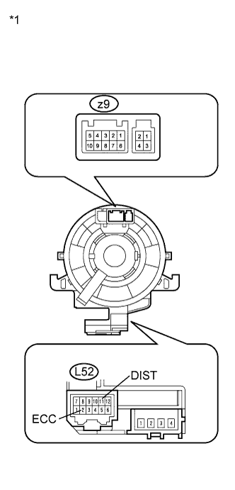
Disconnect the z9 connector from the spiral cable.
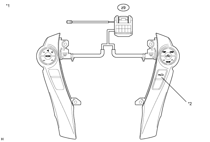
Text in Illustration *1 Component without harness connected
(Steering Pad Switch Assembly)
*2 Distance Control Switch -
Measure the resistance according to the value(s) in the table below.
Standard Resistance Tester Connection Switch Condition Specified Condition z9-4 - z9-6 Distance control switch ON Below 2.5 Ω z9-4 - z9-6 Distance control switch OFF 10 kΩ or higher -
Reinstall the steering pad switch assembly Click here.
-
Proceed to the next step based on the inspection result.
Result Result Proceed to NG A OK B
B
INSPECT SPIRAL WITH SENSOR CABLE SUB-ASSEMBLY Click here
A
REPLACE STEERING PAD SWITCH ASSEMBLY Click here
-
-
INSPECT STEERING PAD SWITCH RH
-
Remove the steering pad switch RH Click here.
-
Disconnect the z9 connector from the spiral cable.
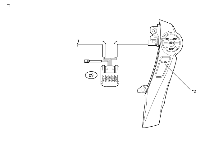
Text in Illustration *1 Component without harness connected
(Steering Pad Switch RH)
*2 Distance Control Switch -
Measure the resistance according to the value(s) in the table below.
Standard Resistance Tester Connection Switch Condition Specified Condition z9-4 - z9-6 Distance control switch ON Below 2.5 Ω z9-4 - z9-6 Distance control switch OFF 10 kΩ or higher -
Reinstall the steering pad switch RH Click here.
NG 
REPLACE STEERING PAD SWITCH RH Click here
OK 
-
-
INSPECT SPIRAL WITH SENSOR CABLE SUB-ASSEMBLY
Note
The spiral with sensor cable sub-assembly is an important part of the SRS airbag system. Incorrect removal or installation of the spiral with sensor cable sub-assembly may cause airbag deployment. Be sure to read the page shown in the brackets.
-
Text in Illustration *1 Component without harness connected
(Spiral with Sensor Cable Sub-assembly)
Remove the spiral with sensor cable sub-assembly Click here.
-
Measure the resistance according to the value(s) in the table below.
Standard Resistance Tester Connection Condition Specified Condition z9-4 - L52-11 (DIST) The spiral with sensor cable sub-assembly is centered Below 1 Ω The spiral with sensor cable sub-assembly position is 2.5 rotations to the left The spiral with sensor cable sub-assembly position is 2.5 rotations to the right z9-6 - L52-2 (ECC) The spiral with sensor cable sub-assembly is centered Below 1 Ω The spiral with sensor cable sub-assembly position is 2.5 rotations to the left The spiral with sensor cable sub-assembly position is 2.5 rotations to the right Tech Tips
The spiral with sensor cable sub-assembly makes a maximum of approximately 5 rotations.
-
Install the spiral with sensor cable sub-assembly Click here.
NG
REPLACE SPIRAL WITH CABLE SUB-ASSEMBLY Click here
OK
-
-
CHECK HARNESS AND CONNECTOR (SPIRAL WITH SENSOR CABLE SUB-ASSEMBLY - DRIVING SUPPORT ECU)
-
Disconnect the driving support ECU connector.
-
Disconnect the spiral with sensor cable sub-assembly connector.
-
Measure the resistance according to the value(s) in the table below.
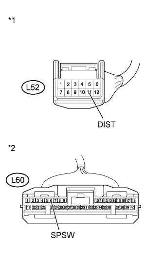
Standard Resistance Tester Connection Condition Specified Condition L60-6 (SPSW) - L52-11 (DIST) Always Below 1 Ω Text in Illustration *1 Front view of wire harness connector
(to Spiral with Sensor Cable Sub-assembly)
*2 Front view of wire harness connector
(to Driving Support ECU)
-
Reconnect the driving support ECU connector.
-
Reconnect the spiral with sensor cable sub-assembly connector.
NG
REPAIR OR REPLACE HARNESS OR CONNECTOR (SPIRAL WITH SENSOR CABLE SUB-ASSEMBLY - DRIVING SUPPORT ECU)
OK
-
-
CHECK HARNESS AND CONNECTOR (SPIRAL WITH SENSOR CABLE SUB-ASSEMBLY - BODY GROUND)
-
Disconnect the spiral with sensor cable sub-assembly connector.
-
Measure the resistance according to the value(s) in the table below.
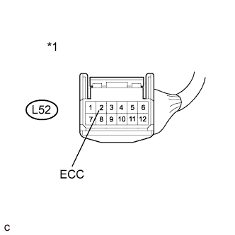
Standard Resistance (Check for Open) Tester Connection Condition Specified Condition L52-2 (ECC) - Body ground Always Below 1 Ω Text in Illustration *1 Front view of wire harness connector
(to Spiral with Sensor Cable Sub-assembly)
-
Reconnect the spiral with sensor cable sub-assembly connector.
NG
REPAIR OR REPLACE HARNESS OR CONNECTOR (SPIRAL WITH SENSOR CABLE SUB-ASSEMBLY - BODY GROUND)
OK
REPLACE DRIVING SUPPORT ECU Click here
-