DYNAMIC RADAR CRUISE CONTROL SYSTEM, Diagnostic DTC:C1A4B

| DTC Code | DTC Name |
|---|---|
| C1A4B | Stop Light Relay Circuit |
DESCRIPTION
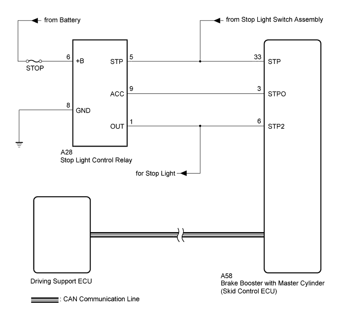
The brake booster with master cylinder (skid control ECU) sends a stop light operation signal to the stop light control relay. When the brake booster with master cylinder (skid control ECU) detects a malfunction in the stop light circuit, the driving support ECU stores DTC C1A4B.
| DTC No. | DTC Detection Condition | Trouble Area |
|---|---|---|
| C1A4B | Either of the following conditions is met:
|
|
WIRING DIAGRAM
INSPECTION PROCEDURE
Note
-
Inspect the fuses for circuits related to this system before performing the following inspection procedure.
-
When this DTC is output, malfunction in the lighting system is suspected. Check if the lighting system is functioning normally Click here.
PROCEDURE
-
CHECK STOP LIGHT OPERATION
-
Check that the stop lights come on when the brake pedal is depressed and go off when the brake pedal is released.
OK Condition Illumination Condition Brake pedal depressed On Brake pedal released Off
NG 
GO TO LIGHTING SYSTEM Click here
OK 
-
-
CHECK TERMINAL VOLTAGE (POWER SOURCE OF STOP LIGHT CONTROL RELAY)
-
Turn the power switch off.
-
Disconnect the A28 stop light control relay connector.
-
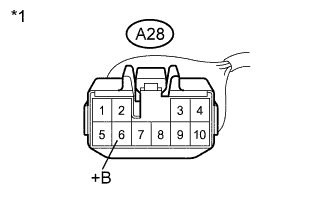
Text in Illustration *1 Front view of wire harness connector
(to Stop Light Control Relay)
Measure the voltage according to the value(s) in the table below.
Standard Voltage Tester Connection Condition Specified Condition A28-6 (+B) - Body ground Always 11 to 14 V
NG
REPAIR OR REPLACE HARNESS OR CONNECTOR
OK
-
-
CHECK HARNESS AND CONNECTOR (STOP LIGHT CONTROL RELAY - BODY GROUND)
-
Turn the power switch off.
-
Disconnect the A28 stop light control relay connector.
-
Measure the resistance according to the value(s) in the table below.
Standard Resistance Tester Connection Condition Specified Condition A28-8 (GND) - Body ground Always Below 1 Ω
NG
REPAIR OR REPLACE HARNESS OR CONNECTOR
OK
-
-
CHECK TERMINAL VOLTAGE (STP TERMINAL)
-
Turn the power switch off.
-
Disconnect the A58 brake booster with master cylinder (skid control ECU) connector.
-
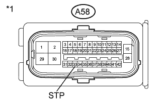
Text in Illustration *1 Front view of wire harness connector
(to Brake Booster with Master Cylinder (Skid Control ECU))
Measure the voltage according to the value(s) in the table below.
Standard Voltage Tester Connection Condition Specified Condition A58-33 (STP) - Body ground Brake pedal depressed 11 to 14 V A58-33 (STP) - Body ground Brake pedal released Below 1.5 V
NG
REPAIR OR REPLACE HARNESS OR CONNECTOR
OK
-
-
CHECK TERMINAL VOLTAGE (STP TERMINAL)
-
Turn the power switch off.
-
Disconnect the A28 stop light control relay connector.
-
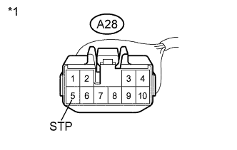
Text in Illustration *1 Front view of wire harness connector
(to Stop Light Control Relay)
Measure the voltage according to the value(s) in the table below.
Standard Voltage Tester Connection Condition Specified Condition A28-5 (STP) - Body ground Brake pedal depressed 11 to 14 V A28-5 (STP) - Body ground Brake pedal released Below 1.5 V
NG
REPAIR OR REPLACE HARNESS OR CONNECTOR
OK
-
-
PERFORM ACTIVE TEST USING INTELLIGENT TESTER (STOP LIGHT RELAY)
-
Enter the following menus: Chassis / ABS/VSC/TRC / Active Test.
-
Perform "Active Test" according to the display on intelligent tester.
Tester Display Measurement Item Control Range Diagnostic Note Stop Light Relay Stop light control relay (STOP LP) ON or OFF Stop lights come on -
Enter the following menus: Chassis / ABS/VSC/TRC / Data List.
Tester Display Measurement Item/Range Normal Condition Diagnostic Note Stop Light Relay Output Stop light control relay (STOP LP) output/
ON or OFF
ON: Relay output on (Stop light on)
OFF: Relay output off (Stop light off)
- Result Result Result Data List item changes between ON and OFF, but stop lights do not turn on A Data List item changes between ON and OFF and stop lights turn on and off B
B 
CHECK HARNESS AND CONNECTOR (SKID CONTROL ECU - STOP LIGHT CONTROL RELAY) Click here
A
-
-
CHECK HARNESS AND CONNECTOR (SKID CONTROL ECU - STOP LIGHT CONTROL RELAY)
-
Turn the power switch off.
-
Disconnect the A58 brake booster with master cylinder (skid control ECU) connector.
-
Disconnect the A28 stop light control relay connector.
-
Measure the resistance according to the value(s) in the table below.
Standard Resistance Tester Connection Condition Specified Condition A58-3 (STPO) - A28-9 (ACC) Always Below 1 Ω A58-3 (STPO) - A28-9 (ACC) Always 10 kΩ or higher
NG
REPAIR OR REPLACE HARNESS OR CONNECTOR
OK
-
-
CHECK HARNESS AND CONNECTOR (SKID CONTROL ECU - STOP LIGHT CONTROL RELAY)
-
Turn the power switch off.
-
Disconnect the A58 brake booster with master cylinder (skid control ECU) connector.
-
Disconnect the A28 stop light control relay connector.
-
Measure the resistance according to the value(s) in the table below.
Standard Resistance Tester Connection Condition Specified Condition A58-6 (STP2) - A28-1 (OUT) Always Below 1 Ω
NG
REPAIR OR REPLACE HARNESS OR CONNECTOR
OK
-
-
CHECK TERMINAL VOLTAGE (STP2 TERMINAL)
-
Turn the power switch off.
-
Disconnect the A58 brake booster with master cylinder (skid control ECU) connector.
-
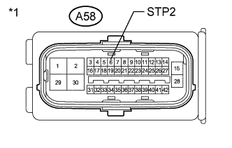
Text in Illustration *1 Front view of wire harness connector
(to Brake Booster with Master Cylinder (Skid Control ECU))
Measure the voltage according to the value(s) in the table below.
Standard Voltage Tester Connection Condition Specified Condition A58-6 (STP2) - Body ground Brake pedal depressed 11 to 14 V A58-6 (STP2) - Body ground Brake pedal released Below 1.5 V
NG
REPLACE STOP LIGHT CONTROL RELAY Click here
OK
-
-
CHECK FOR DTCs (RADAR CRUISE)
-
Turn the power switch off and wait for at least 2 minutes.
-
Clear the DTCs Click here.
-
Make sure that the DTC detection conditions are met.
Tech Tips
If the detection conditions are not met, the system cannot detect the malfunction.
-
Drive the vehicle at a speed of approximately 50 km/h or more with the cruise control switch (ON-OFF button) on.
-
-
Check for DTCs Click here.
Result Result Result DTC C1A4B is not output A DTC C1A4B is output B Note
When replacing the driving support ECU, always replace it with a new one. If a driving support ECU which was installed to another vehicle is used, the information stored in the driving support ECU will not match the information from the vehicle. As a result, a DTC may be stored.
B
REPLACE DRIVING SUPPORT ECU Click here
A 
END
-