DYNAMIC RADAR CRUISE CONTROL SYSTEM, Diagnostic DTC:C1A05

| DTC Code | DTC Name |
|---|---|
| C1A05 | Stop Light Switch Circuit |
DESCRIPTION
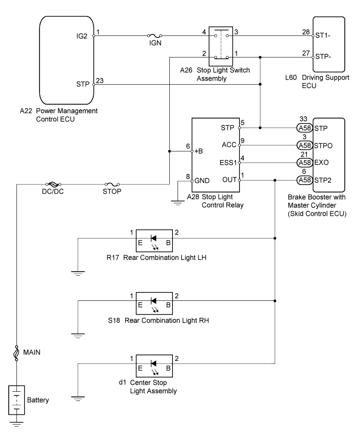
When the brake pedal is depressed, the stop light switch sends a signal to the driving support ECU. Upon receiving the signal, the driving support ECU cancels the dynamic radar cruise control system. Even if there is a malfunction in the stop light signal circuit while the cruise control is operating, normal driving is maintained due to the fail-safe function. Dynamic radar cruise control is canceled when positive battery voltage is applied to terminal STP-.
When the brake pedal is released, positive voltage is applied to terminal ST1- of the driving support ECU through the IGN fuse and the stop light switch, and the driving support ECU operates the dynamic radar cruise control.
The brake booster with master cylinder (skid control ECU) receives a signal from the driving support ECU and operates the brake actuator. The brake booster with master cylinder (skid control ECU) operates the brake actuator and at the same time illuminates the stop lights by operating the stop light control relay.
The stop light switch assembly sends a brake pedal operation signal to the driving support ECU.
After receiving the signal, the ECM performs fail-safe control by canceling the cruise control function.
| DTC No. | DTC Detection Condition | Trouble Area |
|---|---|---|
| C1A05 | Voltages of terminals ST1- and STP- of driving support ECU are both below 1 V for 1 second |
|
WIRING DIAGRAM
INSPECTION PROCEDURE
Tech Tips
Inspect the fuses for circuits related to this system before performing the following inspection procedure.
PROCEDURE
-
CHECK HARNESS AND CONNECTOR (STOP LIGHT SWITCH ASSEMBLY - POWER SOURCE)
-
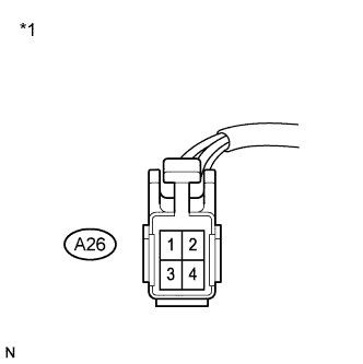
Text in Illustration *1 Front view of wire harness connector
(to Stop Light Switch Assembly)
Disconnect the stop light switch assembly connector.
-
Measure the voltage according to the value(s) in the table below.
Standard Voltage Tester Connection Condition Specified Condition A26-2 - Body ground Always 11 to 14 V -
Reconnect the stop light switch assembly connector.
NG 
CHECK HARNESS AND CONNECTOR (STOP LIGHT SWITCH ASSEMBLY - STOP LIGHT CONTROL RELAY) Click here
OK 
-
-
CHECK HARNESS AND CONNECTOR (STOP LIGHT SWITCH ASSEMBLY - POWER SOURCE)
-
Text in Illustration *1 Front view of wire harness connector
(to Stop Light Switch Assembly)
Disconnect the stop light switch assembly connector.
-
Turn the power switch on (IG).
-
Measure the voltage according to the value(s) in the table below.
Standard Voltage Tester Connection Condition Specified Condition A26-4 - Body ground Power switch on (IG) 11 to 14 V -
Reconnect the stop light switch assembly connector.
NG 
REPAIR OR REPLACE HARNESS OR CONNECTOR (STOP LIGHT SWITCH ASSEMBLY - POWER MANAGEMENT CONTROL ECU)
OK
-
-
INSPECT STOP LIGHT SWITCH ASSEMBLY
-
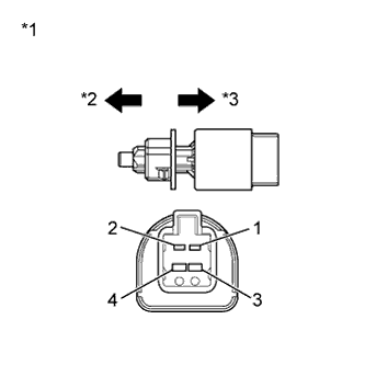
Text in Illustration *1 Component without harness connected
(Stop Light Switch Assembly)
*2 Not pushed *3 Pushed Remove the stop light switch assembly Click here.
-
Measure the resistance according to the value(s) in the table below.
Standard Resistance Tester Connection Switch Condition Specified Condition 1 - 2 Switch pin not pushed Below 1 Ω 3 - 4 Switch pin not pushed 10 kΩ or higher 1 - 2 Switch pin pushed 10 kΩ or higher 3 - 4 Switch pin pushed Below 1 Ω -
Install the stop light switch assembly Click here.
NG
REPLACE STOP LIGHT SWITCH ASSEMBLY Click here
OK
-
-
CHECK HARNESS AND CONNECTOR (STOP LIGHT SWITCH ASSEMBLY - DRIVING SUPPORT ECU)
-
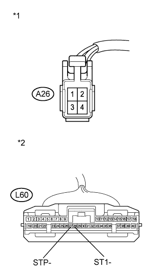
Text in Illustration *1 Front view of wire harness connector
(to Stop Light Switch Assembly)
*2 Front view of wire harness connector
(to Driving Support ECU)
Disconnect the stop light switch assembly connector.
-
Disconnect the driving support ECU connector.
-
Measure the resistance according to the value(s) in the table below.
Standard Resistance (Check for Open) Tester Connection Switch Condition Specified Condition A26-3 - L60-28 (ST1-) Always Below 1 Ω A26-1 - L60-27 (STP-) Always Below 1 Ω Standard Resistance (Check for Open) Tester Connection Switch Condition Specified Condition A26-3 or L60-28 (ST1-) - Body ground Always 10 kΩ or higher A26-1 or L60-27 (STP-) - Body ground Always 10 kΩ or higher -
Reconnect the stop light switch assembly connector.
-
Reconnect the driving support ECU connector.
NG
REPAIR OR REPLACE HARNESS OR CONNECTOR (STOP LIGHT SWITCH ASSEMBLY - DRIVING SUPPORT ECU)
OK
-
-
CHECK HARNESS AND CONNECTOR
-
Disconnect the stop light switch assembly connector.
-
Disconnect the driving support ECU connector.
-
Disconnect the stop light control relay connector.
-
Disconnect the brake booster with master cylinder (skid control ECU) connector.
-
Disconnect the power management control ECU connector.
-
Measure the resistance according to the value(s) in the table below.
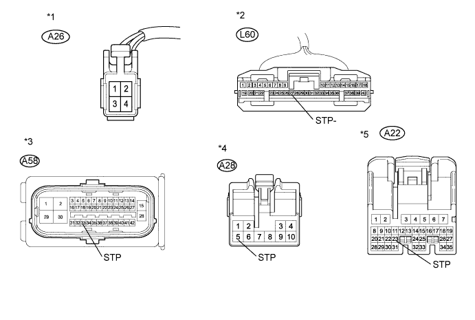
Standard Resistance (Check for Short) Tester Connection Switch Condition Specified Condition A26-1 or L60-27 (STP-) - Body ground Always 10 kΩ or higher A26-1 or A58-33 (STP) - Body ground Always 10 kΩ or higher A26-1 or A28-5 (STP) - Body ground Always 10 kΩ or higher A26-1 or A22-23 (STP) - Body ground Always 10 kΩ or higher Text in Illustration *1 Front view of wire harness connector
(to Stop Light Switch Assembly)
*2 Front view of wire harness connector
(to Driving Support ECU)
*3 Front view of wire harness connector
(to Brake Booster with Master Cylinder (Skid Control ECU))
*4 Front view of wire harness connector
(to Stop Light Control Relay)
*5 Front view of wire harness connector
(to Power Management Control ECU)
- - -
Reconnect the stop light switch assembly connector.
-
Reconnect the driving support ECU connector.
-
Reconnect the power management control ECU connector.
-
Reconnect the stop light control relay connector.
-
Reconnect the brake booster with master cylinder (skid control ECU) connector.
NG
REPAIR OR REPLACE HARNESS OR CONNECTOR
OK 
REPLACE DRIVING SUPPORT ECU Click here
-
-
CHECK HARNESS AND CONNECTOR (STOP LIGHT SWITCH ASSEMBLY - STOP LIGHT CONTROL RELAY)
-
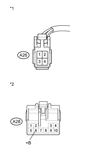
Text in Illustration *1 Front view of wire harness connector
(to Stop Light Switch Assembly)
*2 Front view of wire harness connector
(to Stop Light Control Relay)
Disconnect the stop light switch assembly connector.
-
Disconnect the stop light control relay connector.
-
Measure the resistance according to the value(s) in the table below.
Standard Resistance (Check for Short) Tester Connection Switch Condition Specified Condition A26-2 or A28-6 (+B) - Body ground Always 10 kΩ or higher -
Reconnect the stop light switch assembly connector.
-
Reconnect the stop light control relay connector.
NG
REPAIR OR REPLACE HARNESS OR CONNECTOR (STOP LIGHT SWITCH ASSEMBLY - STOP LIGHT CONTROL RELAY)
OK
REPAIR OR REPLACE HARNESS OR CONNECTOR (STOP LIGHT SWITCH ASSEMBLY - BATTERY)
-