CRUISE CONTROL SYSTEM TERMINALS OF ECU

-
CHECK POWER MANAGEMENT CONTROL ECU
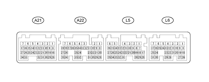
Terminal No. (Symbol) Wiring Color Terminal Description Condition Specified Condition A22-7 (ST1-) - L5-6 (E1) R - BR Stop light switch signal Power switch on (IG), Brake pedal released 7.5 to 14 V A22-7 (ST1-) - L5-6 (E1) R - BR Stop light switch signal Power switch on (IG), Brake pedal depressed Below 1 V A22-23 (STP) - L5-6 (E1) L - BR Stop light switch signal Brake pedal released Below 1 V A22-23 (STP) - L5-6 (E1) L - BR Stop light switch signal Brake pedal depressed 7.5 to 14 V L5-6 (E1) - Body ground BR - Body ground Earth (ground) circuit of power management control ECU Always Below 1 Ω L5-11(TC) - L5-6 (E1) P - BR Terminal TC of DLC3 Power switch on (IG) 11 to 14 V L5-11(TC) - L5-6 (E1) P - BR Terminal TC of DLC3 Terminals TC and CG of DLC3 connected Below 1 V L5-14 (SPDI) - L5-6 (E1) V - BR Vehicle speed signal Driving at 20 km/h (12 mph) Pulse generation
(see waveform 1)
L6-22 (CCS) - L5-6 (E1) R - BR Cruise control main switch circuit Power switch on (IG) 10 to 14 V L6-22 (CCS) - L5-6 (E1) R - BR Cruise control main switch circuit Power switch on (IG), MAIN switch on Below 1 V L6-22 (CCS) - L5-6 (E1) R - BR Cruise control main switch circuit Power switch on (IG), + RES switch on 2.3 to 4.0 V L6-22 (CCS) - L5-6 (E1) R - BR Cruise control main switch circuit Power switch on (IG), - SET switch on 4.5 to 7.1 V L6-22 (CCS) - L5-6 (E1) R - BR Cruise control main switch circuit Power switch on (IG), CANCEL switch on 6.6 to 10.1 V L6-24 (CA1L) - L5-6 (E1) W - BR CAN communication line Power switch on (IG) Pulse generation
(see waveform 2)
L6-25 (CA1H) - L5-6 (E1) B - BR CAN communication line Power switch on (IG) Pulse generation
(see waveform 3)
-
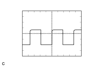
WAVEFORM 1
-
Vehicle speed signal
Power Management Control ECU Terminal Name Between SPDI and E1 Tester Range 5 V/DIV., 20 ms./DIV. Condition Driving at 20 km/h (12 mph) Tech Tips
-
The wavelength becomes shorter as the vehicle speed increases.
-
Depending on the vehicle, the output waveform voltage may rise to 12 V if influenced by optionally installed systems.
-
-
-
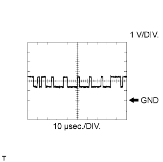
WAVEFORM 2
-
CAN communication signal
Power Management Control ECU Terminal Name Between CA1L and E1 Tester Range 1 V/DIV., 10 μsec./DIV. Condition Power switch on (IG) Tech Tips
The waveform varies depending on the CAN communication signal.
-
-
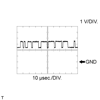
WAVEFORM 3
-
CAN communication signal
Power Management Control ECU Terminal Name Between CA1H and E1 Tester Range 1 V/DIV., 10 μsec./DIV. Condition Power switch on (IG) Tech Tips
The waveform varies depending on the CAN communication signal.
-
-