POWER SWITCH INSTALLATION

-
INSTALL POWER SWITCH
-
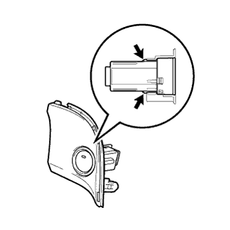
Attach the 2 claws to install the power switch.
-
-
INSTALL UPPER INSTRUMENT PANEL FINISH PANEL SUB-ASSEMBLY
-
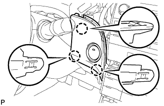
Connect the connector.
-
Engage the 3 claws to install the upper instrument panel finish panel sub-assembly.
-
-
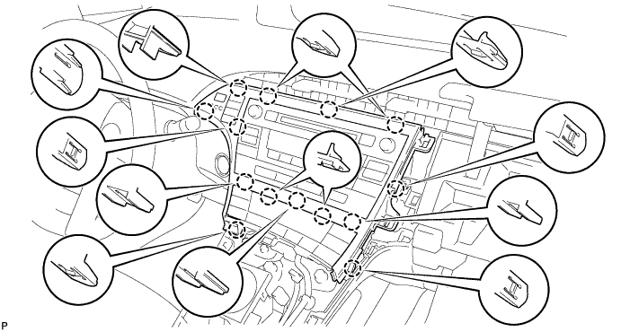
INSTALL INSTRUMENT CLUSTER FINISH PANEL GARNISH
-
Connect the connector.
-
Engage the 14 claws to install the instrument cluster finish panel garnish.
-
-
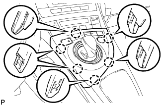
INSTALL LOWER CENTER INSTRUMENT CLUSTER FINISH PANEL SUB-ASSEMBLY
-
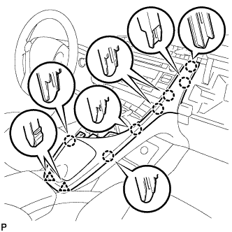
Engage the 7 claws and 2 clips to install the lower center instrument cluster finish panel sub-assembly.
-
-
INSTALL INTEGRATION CONTROL AND PANEL ASSEMBLY
-
Connect each connector.
-
Engage the 6 claws to install the integration control and panel assembly.
-
-
CONNECT CABLE TO NEGATIVE BATTERY TERMINAL
Note
When disconnecting the cable, some systems need to be initialized after the cable is reconnected Click here.
-
INSTALL REAR NO. 3 FLOOR BOARD
-

Engage the 2 guides to install the rear No. 3 floor board.
-
-
INSTALL REAR DECK FLOOR BOX
-
Install the rear deck floor box.
-
-
INSTALL REAR NO. 2 FLOOR BOARD
-

Engage the 3 guides <A>.
-
Engage the 2 guides <B> and install the rear No. 2 floor board as shown in the illustration.
-