COOLING FAN SYSTEM Cooling Fan Circuit
DESCRIPTION
The ECM turns on or off the fan relays using signals calculated from the engine coolant temperature, air conditioning switch (on/off), air conditioning refrigerant pressure, engine speed, and vehicle speed signals.
The ECM switches the circuit of the cooling fan motors between series and parallel by turning on or off the fan relays in order to control the speed of the cooling fan motors in two steps.
WIRING DIAGRAM
Refer to System Diagram Click here.
INSPECTION PROCEDURE
Note
Inspect the fuses for circuits related to this system before performing the following inspection procedure.
PROCEDURE
-
PERFORM ACTIVE TEST USING INTELLIGENT TESTER (CONTROL THE ELECTRIC COOLING FAN)
-
Connect the intelligent tester to the DLC3.
-
Turn the power switch on (IG).
-
Turn the tester on.
-
Enter the following menus: Powertrain / Engine and ECT / Active Test / Control the Electric Cooling Fan.
OK Tester Operation Specified Condition ON Fans operate OFF Fans do not operate
NG 
INSPECT ECM (FANL AND FANH VOLTAGE) Click here
OK 
PROCEED TO NEXT SUSPECTED AREA SHOWN IN PROBLEM SYMPTOMS TABLE Click here
-
-
INSPECT ECM (FANL AND FANH VOLTAGE)
-
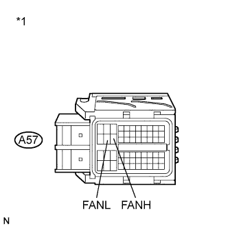
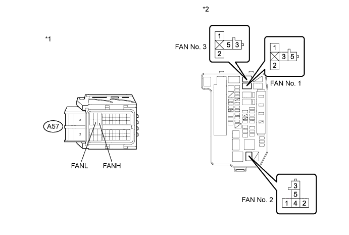
Text in Illustration *1 Front view of wire harness connector
(to ECM)
Disconnect the ECM connector.
-
Turn the power switch on (IG).
-
Measure the voltage according to the value(s) in the table below.
Standard Voltage Tester Connection Switch Condition Specified Condition A57-22 (FANH) - Body ground Power switch on (IG) 11 to 14 V A57-21 (FANL) - Body ground Power switch on (IG) 11 to 14 V -
Reconnect the ECM connector.
NG
CHECK FUSE (ECU-IG NO. 1 FUSE VOLTAGE) Click here
OK 
-
-
INSPECT ENGINE ROOM RELAY BLOCK (FAN NO. 1 RELAY AND FAN NO. 3 RELAY VOLTAGE)
-
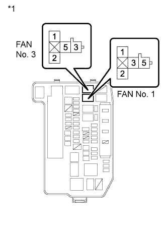
Text in Illustration *1 Engine Room Relay Block Remove the FAN No. 1 relay and FAN No. 3 relay from the engine room relay block.
-
Measure the voltage according to the value(s) in the table below.
Standard Voltage Tester Connection Condition Specified Condition 3 (FAN No. 1 relay) - Body ground Always 11 to 14 V 5 (FAN No. 3 relay) - Body ground Always 11 to 14 V -
Reinstall the FAN No. 1 relay and FAN No. 3 relay.
NG 
REPAIR OR REPLACE HARNESS OR CONNECTOR (BATTERY - ENGINE ROOM RELAY BLOCK)
OK
-
-
INSPECT FAN NO. 1 RELAY
-
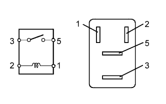
Remove the FAN No. 1 relay from the engine room relay block.
-
Measure the resistance according to the value(s) in the table below.
Standard Resistance Tester Connection Condition Specified Condition 3 - 5 Battery voltage is not applied between terminals 1 and 2 10 kΩ or higher Battery voltage is applied between terminals 1 and 2 Below 1 Ω -
Reinstall the FAN No. 1 relay.
NG
REPLACE FAN NO. 1 RELAY
OK
-
-
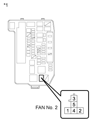
INSPECT FAN NO. 2 RELAY
-
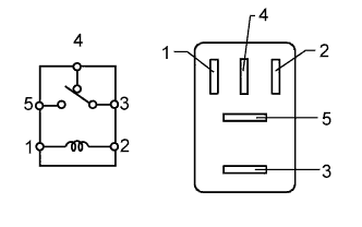
Remove the FAN No. 2 relay from the engine room relay block.
-
Measure the resistance according to the value(s) in the table below.
Standard Resistance Tester Connection Condition Specified Condition 3 - 4 Battery voltage is not applied between terminals 1 and 2 Below 1 Ω Battery voltage is applied between terminals 1 and 2 10 kΩ or higher 3 - 5 Battery voltage is not applied between terminals 1 and 2 10 kΩ or higher Battery voltage is applied between terminals 1 and 2 Below 1 Ω -
Reinstall the FAN No. 2 relay.
NG
REPLACE FAN NO. 2 RELAY
OK
-
-
INSPECT FAN NO. 3 RELAY
-
Remove the FAN No. 3 relay from the engine room relay block.
-
Measure the resistance according to the value(s) in the table below.
Standard Resistance Tester Connection Condition Specified Condition 3 - 5 Battery voltage is not applied between terminals 1 and 2 10 kΩ or higher Battery voltage is applied between terminals 1 and 2 Below 1 Ω -
Reinstall the FAN No. 3 relay.
NG
REPLACE FAN NO. 3 RELAY
OK
-
-
CHECK HARNESS AND CONNECTOR (FAN NO. 2 RELAY - BODY GROUND)
-
Text in Illustration *1 Engine Room Relay Block Remove the FAN No. 2 relay from the engine room relay block.
-
Measure the resistance according to the value(s) in the table below.
Standard Resistance (Check for Open) Tester Connection Condition Specified Condition 5 (FAN No. 2 relay) - Body ground Always Below 1 Ω -
Reinstall the FAN No. 2 relay.
NG
REPAIR OR REPLACE HARNESS OR CONNECTOR (FAN NO. 2 RELAY - BODY GROUND)
OK
-
-
INSPECT COOLING FAN MOTOR
-
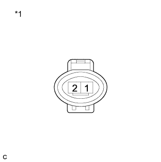
Text in Illustration *1 Component without harness connected
(Cooling Fan Motor)
Disconnect the cooling fan motor connector.
-
Check that the cooling fan motor operates smoothly when the battery is connected to the cooing fan motor connector.
-
Measure the current while the motor is operating.
Standard Current Tester Connection Condition Specified Condition 1 - 2 Always 11.2 to 14.5 A -
Reconnect the cooling fan motor connector.
NG
REPLACE COOLING FAN MOTOR Click here
OK
-
-
CHECK HARNESS AND CONNECTOR (COOLING FAN MOTOR - BODY GROUND)
-
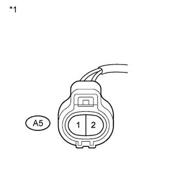
Text in Illustration *1 Front view of wire harness connector
(to Cooling Fan Motor)
Disconnect the cooling fan motor connector.
-
Measure the resistance according to the value(s) in the table below.
Standard Resistance (Check for Open) Tester Connection Condition Specified Condition A5-1 - Body ground Always Below 1 Ω -
Reconnect the cooling fan motor connector.
NG
REPAIR OR REPLACE HARNESS OR CONNECTOR (COOLING FAN MOTOR - BODY GROUND)
OK
-
-
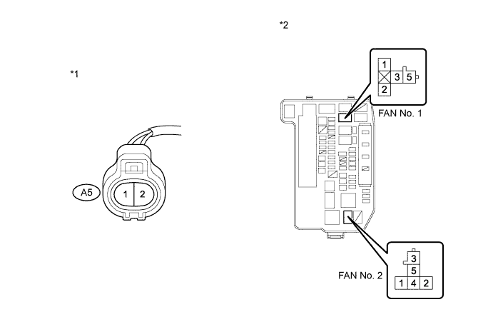
CHECK HARNESS AND CONNECTOR (COOLING FAN MOTOR - ENGINE ROOM RELAY BLOCK)
-
Disconnect the cooling fan motor connector.
-
Remove the FAN No. 1 relay and FAN No. 2 relay from the engine room relay block.
-
Measure the resistance according to the value(s) in the table below.
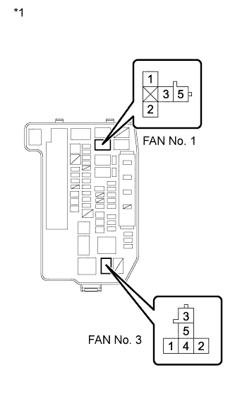
Standard Resistance (Check for Open) Tester Connection Condition Specified Condition A5-2 - 5 (FAN No. 1 relay) Always Below 1 Ω A5-2 - 4 (FAN No. 2 relay) Always Below 1 Ω Standard Resistance (Check for Short) Tester Connection Condition Specified Condition A5-2 or 5 (FAN No. 1 relay) - Body ground Always 10 kΩ or higher A5-2 or 4 (FAN No. 2 relay) - Body ground Always 10 kΩ or higher Text in Illustration *1 Front view of wire harness connector
(to Cooling Fan Motor)
*2 Engine Room Relay Block -
Reconnect the cooling fan motor connector.
-
Reinstall the FAN No. 1 relay and FAN No. 2 relay.
NG
REPAIR OR REPLACE HARNESS OR CONNECTOR (COOLING FAN MOTOR - ENGINE ROOM RELAY BLOCK)
OK
-
-
INSPECT NO. 2 COOLING FAN MOTOR
-
Text in Illustration *1 Component without harness connected
(No. 2 Cooling Fan Motor)
Disconnect the No. 2 cooling fan motor connector.
-
Check that the No. 2 cooling fan motor operates smoothly when the battery is connected to the No. 2 cooling fan motor connector.
-
Measure the current while the motor is operating.
Standard Current Tester Connection Condition Specified Condition 1 - 2 Always 7.4 to 10.9 A -
Reconnect the No. 2 cooling fan fan motor connector.
NG
REPLACE NO. 2 COOLING FAN MOTOR Click here
OK
-
-
CHECK HARNESS AND CONNECTOR (NO. 2 COOLING FAN MOTOR - ENGINE ROOM RELAY BLOCK)
-
Disconnect the No. 2 cooling fan motor connector.
-
Remove the FAN No. 2 relay and FAN No. 3 relay from the engine room relay block.
-
Measure the resistance according to the value(s) in the table below.
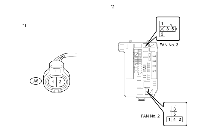
Standard Resistance (Check for Open) Tester Connection Condition Specified Condition A6-1 - 3 (FAN No. 2 relay) Always Below 1 Ω A6-2 - 3 (FAN No. 3 relay) Always Below 1 Ω Standard Resistance (Check for Short) Tester Connection Condition Specified Condition A6-1 or 3 (FAN No. 2 relay) - Body ground Always 10 kΩ or higher A6-2 or 3 (FAN No. 3 relay) - Body ground Always 10 kΩ or higher Text in Illustration *1 Front view of wire harness connector
(to No. 2 Cooling Fan Motor)
*2 Engine Room Relay Block -
Reconnect the No. 2 cooling fan motor connector.
-
Reinstall the FAN No. 2 relay and FAN No. 3 relay.
NG
REPAIR OR REPLACE HARNESS OR CONNECTOR (NO. 2 COOLING FAN MOTOR - ENGINE ROOM RELAY BLOCK)
OK
-
-
INSPECT ENGINE ROOM RELAY BLOCK (FAN NO. 1 RELAY - FAN NO. 2 RELAY)
-
Text in Illustration *1 Engine Room Relay Block Remove the FAN No. 1 relay and FAN No. 2 relay from the engine room relay block.
-
Measure the resistance according to the value(s) in the table below.
Standard Resistance (Check for Open) Tester Connection Condition Specified Condition 1 (FAN No. 1 relay) - 1 (FAN No. 2 relay) Always Below 1 Ω 2 (FAN No. 1 relay) - 2 (FAN No. 2 relay) Always Below 1 Ω Standard Resistance (Check for Short) Tester Connection Condition Specified Condition 1 (FAN No. 1 relay) or 1 (FAN No. 2 relay) - Body ground Always 10 kΩ or higher 2 (FAN No. 1 relay) or 2 (FAN No. 2 relay) - Body ground Always 10 kΩ or higher -
Reinstall the FAN No. 1 relay and FAN No. 2 relay.
NG
REPLACE ENGINE ROOM RELAY BLOCK
OK
REPLACE ECM Click here
-
-
CHECK FUSE (ECU-IG NO. 1 FUSE VOLTAGE)
-
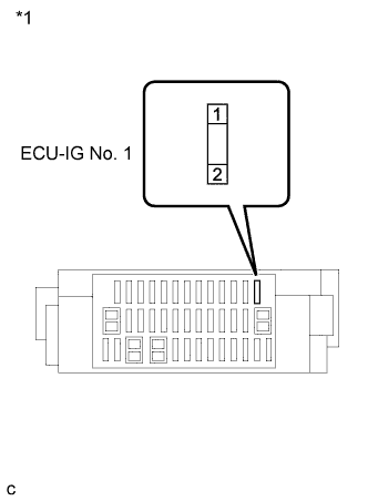
Text in Illustration *1 Instrument Panel Junction Block Assembly Remove the ECU-IG No. 1 fuse from the instrument panel junction block.
-
Turn the power switch on (IG).
-
Measure the voltage according to the value(s) in the table below.
Standard Voltage Tester Connection Switch Condition Specified Condition 1 (ECU-IG No. 1 fuse) - Body ground Power switch on (IG) 11 to 14 V -
Reinstall the ECU-IG No. 1 fuse.
NG
INSPECT INSTRUMENT PANEL JUNCTION BLOCK ASSEMBLY (IG1 NO. 1 RELAY) Click here
OK
-
-
INSPECT INSTRUMENT PANEL JUNCTION BLOCK ASSEMBLY
-
Disconnect the instrument panel junction block assembly connector.
-
Remove the ECU-IG No. 1 fuse from the instrument panel junction block assembly.
-
Measure the resistance according to the value(s) in the table below.
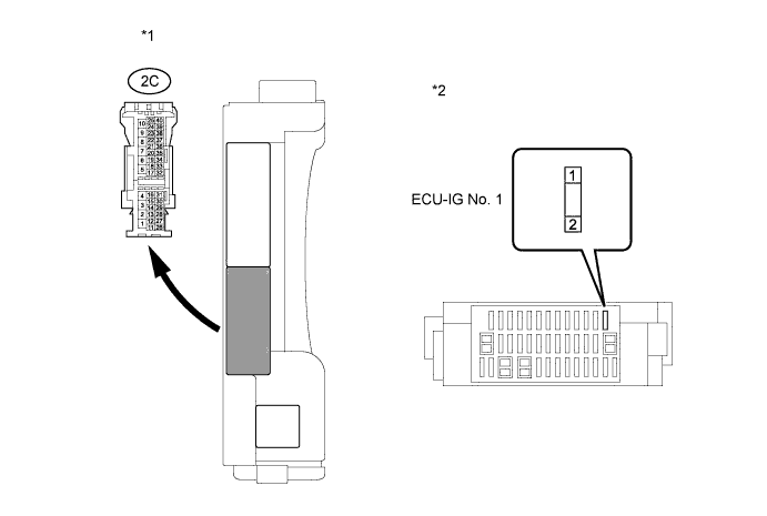
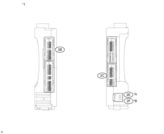
Standard Resistance (Check for Open) Tester Connection Condition Specified Condition 2C-30 - 2 (ECU-IG No. 1) Always Below 1 Ω Standard Resistance (Check for Short) Tester Connection Condition Specified Condition 2C-30 or 2 (ECU-IG No. 1) - Body ground Always 10 kΩ or higher Text in Illustration *1 Component without harness connected
(Instrument Panel Junction Block Assembly)
*2 Instrument Panel Junction Block Assembly -
Reconnect the ECU-IG No. 1 fuse.
-
Reconnect the instrument panel junction block assembly connector.
NG
REPLACE INSTRUMENT PANEL JUNCTION BLOCK ASSEMBLY
OK
-
-
INSPECT FAN NO. 1 RELAY
-
Remove the FAN No. 1 relay from the engine room relay block.
-
Measure the resistance according to the value(s) in the table below.
Standard Resistance Tester Connection Condition Specified Condition 3 - 5 Battery voltage is not applied between terminals 1 and 2 10 kΩ or higher Battery voltage is applied between terminals 1 and 2 Below 1 Ω -
Reinstall the FAN No. 1 relay.
NG
REPLACE FAN NO. 1 RELAY
OK
-
-
INSPECT FAN NO. 2 RELAY
-
Remove the FAN No. 2 relay from the engine room relay block.
-
Measure the resistance according to the value(s) in the table below.
Standard Resistance Tester Connection Condition Specified Condition 3 - 4 Battery voltage is not applied between terminals 1 and 2 Below 1 Ω Battery voltage is applied between terminals 1 and 2 10 kΩ or higher 3 - 5 Battery voltage is not applied between terminals 1 and 2 10 kΩ or higher Battery voltage is applied between terminals 1 and 2 Below 1 Ω -
Reinstall the FAN No. 2 relay.
NG
REPLACE FAN NO. 2 RELAY
OK
-
-
INSPECT FAN NO. 3 RELAY
-
Remove the FAN No. 3 relay from the engine room relay block.
-
Measure the resistance according to the value(s) in the table below.
Standard Resistance Tester Connection Condition Specified Condition 3 - 5 Battery voltage is not applied between terminals 1 and 2 10 kΩ or higher Battery voltage is applied between terminals 1 and 2 Below 1 Ω -
Reinstall the FAN No. 3 relay.
NG
REPLACE FAN NO. 3 RELAY
OK
-
-
CHECK HARNESS AND CONNECTOR (ENGINE ROOM RELAY BLOCK - ECM)
-
Remove the FAN No. 1 relay, FAN No. 2 relay and FAN No. 3 relay from the engine room relay block.
-
Disconnect the ECM connector.
-
Measure the resistance according to the value(s) in the table below.
Standard Resistance (Check for Open) Tester Connection Condition Specified Condition 2 (FAN No. 1 relay) - A57-22 (FANH) Always Below 1 Ω 2 (FAN No. 2 relay) - A57-22 (FANH) Always Below 1 Ω 2 (FAN No. 3 relay) - A57-21 (FANL) Always Below 1 Ω Standard Resistance (Check for Short) Tester Connection Condition Specified Condition 2 (FAN No. 1 relay) or A57-22 (FANH) - Body ground Always 10 kΩ or higher 2 (FAN No. 2 relay) or A57-22 (FANH) - Body ground Always 10 kΩ or higher 2 (FAN No. 3 relay) or A57-21 (FANL) - Body ground Always 10 kΩ or higher Text in Illustration *1 Front view of wire harness connector
(to ECM)
*2 Engine Room Relay Block -
Reinstall the FAN No. 1 relay, FAN No. 2 relay and FAN No. 3 relay.
-
Reconnect the ECM connector.
NG
REPAIR OR REPLACE HARNESS OR CONNECTOR (ENGINE ROOM RELAY BLOCK - ECM)
OK
REPAIR OR REPLACE HARNESS OR CONNECTOR (ECU-IG NO. 1 FUSE - ENGINE ROOM RELAY BLOCK)
-
-
INSPECT INSTRUMENT PANEL JUNCTION BLOCK ASSEMBLY (IG1 NO. 1 RELAY)
-
Disconnect the instrument panel junction block assembly connector.
-
Measure the resistance according to the value(s) in the table below.
Standard Resistance (for LHD) Tester Connection Condition Specified Condition 2E-1 - 2C-30 Battery voltage is not applied between terminals 2B-25 - 2B-6 10 kΩ or higher Battery voltage is applied between terminals 2B-25 - 2B-6 Below 1 Ω Standard Resistance (for RHD) Tester Connection Condition Specified Condition 2F-1 - 2C-30 Battery voltage is not applied between terminals 2B-25 - 2B-6 10 kΩ or higher Battery voltage is applied between terminals 2B-25 - 2B-6 Below 1 Ω Text in Illustration *A for LHD *B for RHD *1 Component without harness connected
(to Instrument Panel Junction Block Assembly)
-
Reconnect the instrument panel junction block assembly connector.
NG
REPLACE INSTRUMENT PANEL JUNCTION BLOCK ASSEMBLY (IG1 NO. 1 RELAY)
OK
-
-
INSPECT INSTRUMENT PANEL JUNCTION BLOCK ASSEMBLY (IG1 NO. 1 RELAY VOLTAGE)
-
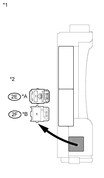
Text in Illustration *A for LHD *B for RHD *1 Instrument Panel Junction Block Assembly *2 Front view of wire harness connector
(to Instrument Panel Junction Block Assembly)
Disconnect the instrument panel junction block assembly connector.
-
Measure the voltage according to the value(s) in the table below.
Standard Voltage (for LHD) Tester Connection Condition Specified Condition 2E-1 - Body ground Always 11 to 14 V Standard Voltage (for RHD) Tester Connection Condition Specified Condition 2F-1 - Body ground Always 11 to 14 V -
Reconnect the instrument panel junction block assembly connector.
NG
REPAIR OR REPLACE HARNESS OR CONNECTOR (BATTERY - INSTRUMENT PANEL JUNCTION BLOCK ASSEMBLY)
OK
-
-
CHECK HARNESS AND CONNECTOR (IG1 NO. 1 RELAY - BODY GROUND)
-
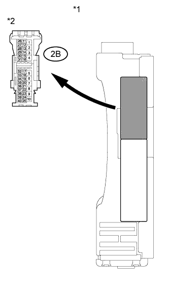
Text in Illustration *1 Instrument Panel Junction Block Assembly *2 Front view of wire harness connector
(to Instrument Panel Junction Block Assembly)
Disconnect the instrument panel junction block assembly connector.
-
Measure the resistance according to the value(s) in the table below.
Standard Resistance Tester Connection Condition Specified Condition 2B-6 - Body ground Always Below 1 Ω -
Reconnect the instrument panel junction block assembly connector.
NG
REPAIR OR REPLACE HARNESS OR CONNECTOR (IG1 NO. 1 RELAY - BODY GROUND)
OK
-
-
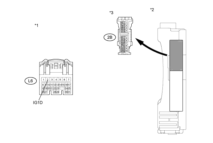
CHECK HARNESS AND CONNECTOR (IG1 NO. 1 RELAY - POWER MANAGEMENT CONTROL ECU)
-
Disconnect the instrument panel junction block assembly connector.
-
Disconnect the power management control ECU connector.
-
Measure the resistance according to the value(s) in the table below.
Standard Resistance (Check for Open) Tester Connection Condition Specified Condition L6-2 (IG1D) - 2B-25 Always Below 1 Ω Standard Resistance (Check for Short) Tester Connection Condition Specified Condition L6-2 (IG1D) or 2B-25 - Body ground Always 10 kΩ or higher Text in Illustration *1 Front view of wire harness connector
(to Power Management Control ECU)
*2 Instrument Panel Junction Block Assembly *3 Front view of wire harness connector
(to Instrument Panel Junction Block Assembly)
- - -
Reconnect the instrument panel junction block assembly connector.
-
Reconnect the power management control ECU connector.
NG
REPAIR OR REPLACE HARNESS OR CONNECTOR (IG1 NO. 1 RELAY - POWER MANAGEMENT CONTROL ECU)
OK
CHECK ENTRY AND START SYSTEM Click here
-