RADIATOR REMOVAL

-
PRECAUTION (w/ Navigation System for HDD)
Note
After the power switch is turned off, the display and navigation module display (HDD navigation system) records various types of memory and settings. As a result, after turning the power switch off, make sure to wait at least 60 seconds before disconnecting the cable from the negative (-) battery terminal.
-
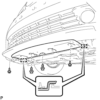
REMOVE RADIATOR SUPPORT OPENING COVER
-
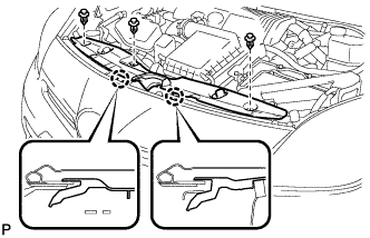
Remove the 3 clips.
-
Disengage the 2 claws and remove the radiator support opening cover.
-
-
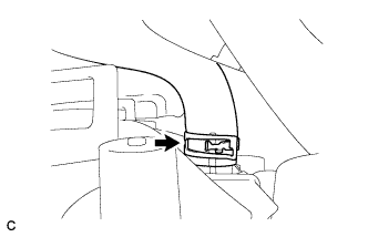
REMOVE REAR NO. 2 FLOOR BOARD
-

Disengage the 2 guides <A> as shown in the illustration.
-
Disengage the 3 guides <B> and remove the rear No. 2 floor board.
-
-
REMOVE REAR DECK FLOOR BOX
-
Remove the rear deck floor box.
-
-
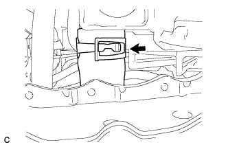
REMOVE REAR NO. 3 FLOOR BOARD
-

Disengage the 2 guides and remove the rear No. 3 floor board.
-
-
DISCONNECT CABLE FROM NEGATIVE BATTERY TERMINAL
Note
When disconnecting the cable, some systems need to be initialized after the cable is reconnected Click here.
-
REMOVE FRONT SPOILER COVER (w/ Front Spoiler)
-
REMOVE ENGINE UNDER COVER
-
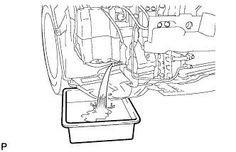
DRAIN COOLANT (for Engine)
Note
Do not remove the reservoir tank cap, cylinder block drain cock plugs and radiator drain cock plug while the engine and radiator are still hot. Pressurized, hot engine coolant and steam may be released and cause serious burns.
-
Loosen the radiator drain cock plug and drain the coolant.
Text in Illustration *1 Reservoir Tank Cap *2 Radiator Drain Cock Plug Tech Tips
Collect the coolant in a container and dispose of it according to the local regulations.
-
-
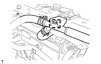
DISCONNECT NO. 1 RADIATOR HOSE
-
Disconnect the No. 1 radiator hose from the radiator assembly.
-
-
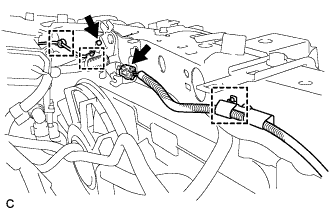
DISCONNECT NO. 2 RADIATOR HOSE
-
Disconnect the No. 2 radiator hose from the radiator assembly.
-
-
REMOVE FRONT BUMPER ASSEMBLY
-
Text in Illustration *1 Protective Tape Put protective tape around the front bumper assembly.
Tech Tips
Use the same procedure for the RH side and LH side.
-
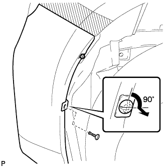
Using a screwdriver, turn the pin 90 degrees and remove the pin hold clip.
Tech Tips
Use the same procedure for the RH side and LH side.
-
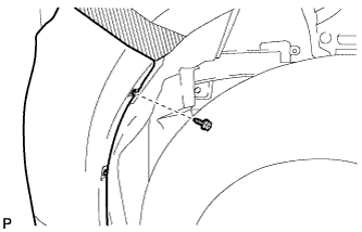
Remove the screw.
Tech Tips
Use the same procedure for the RH side and LH side.
-
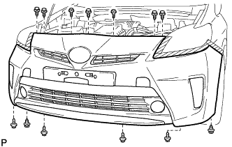
Remove the 2 bolts and 4 screws.
-
Using a clip remover, remove the 7 clips.
-
w/ Front Spoiler:
-
Using a clip remover, remove the 2 clips.
-
Remove the 2 screws.
-
Disengage the 2 guides and remove the front spoiler cover.
-
-
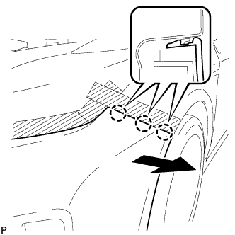
Disengage the 3 claws and remove the front bumper assembly.
Tech Tips
Use the same procedure for the RH side and LH side.
-
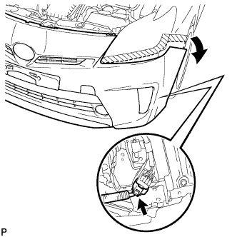
Pull back the side of the front bumper assembly as shown in the illustration and disconnect the connector.
Note
Do not apply excessive force when separating the front bumper.
-
w/ Headlight Cleaner System:
-
Disconnect the headlight cleaner hose and drain the washer fluid.
Tech Tips
Use a container to collect the washer fluid.
-
-
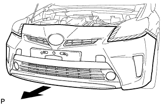
Remove the front bumper assembly as shown in the illustration.
-
-
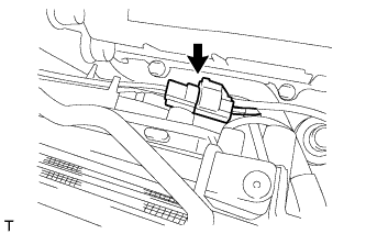
REMOVE MILLIMETER WAVE RADAR SENSOR ASSEMBLY (w/ Dynamic Radar Cruise Control System)
-
Disconnect the connector.
-
Remove the 5 bolts and millimeter wave radar sensor assembly.
-
-
REMOVE MILLIMETER WAVE RADAR SENSOR BRACKET
-
Remove the bolt and millimeter wave radar sensor bracket.
-
-
REMOVE NO. 1 INVERTER BRACKET
-
Remove the 3 bolts and No. 1 inverter bracket.
-
-
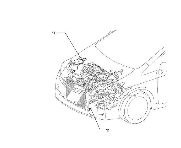
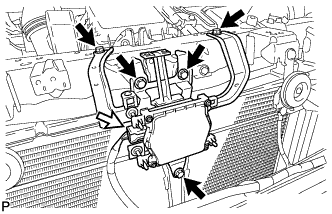
REMOVE HOOD LOCK SUPPORT SUB-ASSEMBLY
-
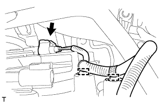
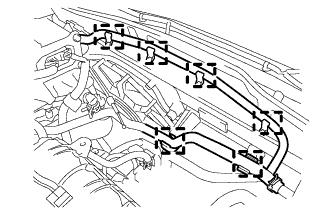
Disconnect the water by-pass hose clamp from the radiator support RH.
-
Disconnect the hood lock connector and hood lock control cable wire.
-
Disconnect the 3 wire harness clamps.
-
Disconnect the connector from the No. 2 cooling fan motor.
-
Disconnect the 2 wire harness clamps and connector from the fan shroud and cooling fan motor.
-
Disconnect the 2 horn connectors.
-
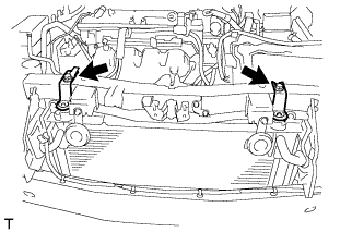
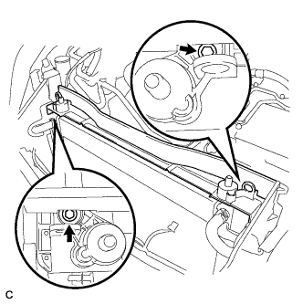
Remove the 2 bolts, radiator support RH and radiator support LH with the 2 cushions from the upper radiator support.
-
Remove the 4 bolts and upper radiator support.
-
-
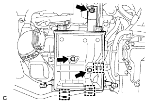
REMOVE AIR CLEANER CAP SUB-ASSEMBLY
-
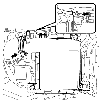
Disconnect the air flow meter connector.
-
Disconnect the 2 clamps and hose band, and remove the air cleaner cap sub-assembly.
-
Remove the air cleaner filter element.
-
-
REMOVE INLET AIR CLEANER ASSEMBLY
-
Remove the 2 bolts and inlet air cleaner assembly.
-
-
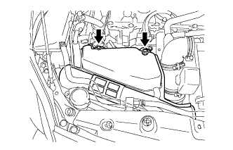
REMOVE AIR CLEANER CASE
-
Separate the No. 4 water by-pass hose from the air cleaner case.
-
Remove the 3 bolts and air cleaner case.
-
-
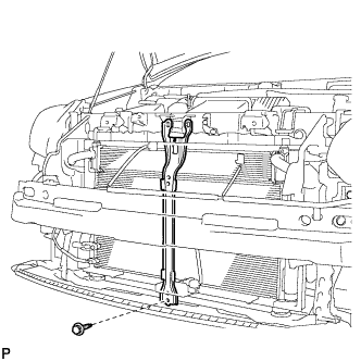
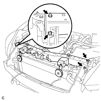
REMOVE NO. 2 FAN SHROUD
-
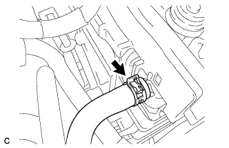
Disconnect the No. 1 water by-pass hose from the radiator assembly.
-
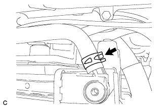
Disconnect the water by-pass hose from the radiator assembly.
-
Disconnect the 6 water by-pass hose clamps from the No. 2 fan shroud.
-
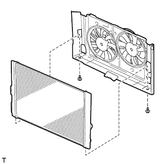
Remove the 2 bolts and No. 2 fan shroud from the radiator assembly.
-
-
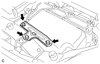
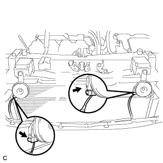
REMOVE RADIATOR ASSEMBLY
-

Remove the radiator assembly with the fan shroud.
Note
For vehicles with the air conditioning system, do not apply any excessive force to the cooler condenser assembly or pipe when removing the radiator assembly.
-
Remove the 2 lower radiator supports.
-
Remove the 2 bolts.
-
Remove the fan shroud from the radiator assembly.
-