EGR COOLER INSTALLATION

-
INSTALL EGR WITH COOLER PIPE SUB-ASSEMBLY
-
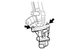
Temporarily install a new gasket and EGR valve assembly to the EGR with cooler pipe sub-assembly with the 2 nuts.
-
Install a new gasket and set the EGR valve with cooler assembly in place.
-
Using an E8 "TORX" socket wrench, install the 4 stud bolts.
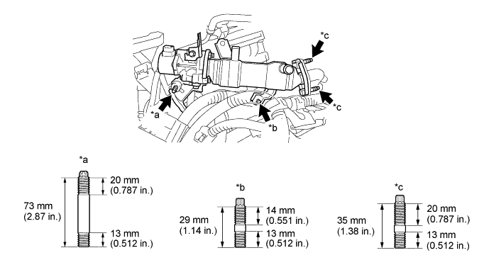
Text in Illustration *a Stud Bolt A *b Stud Bolt B *c Stud Bolt C - - - Torque:
- Stud bolt A and stud bolt B
- 9.5 N*m { 97 kgf*cm, 84 in.*lbf }
- Stud bolt C
- 5.0 N*m { 51 kgf*cm, 44 in.*lbf }
If a stud bolt is deformed or the threads are damaged, replace it.
-
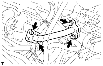
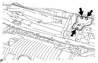
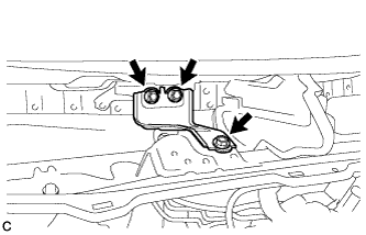
Temporarily install the 2 nuts (B), 2 nuts (C) and bolt.
Tech Tips
The type B and type C of the nut (C) are non-reusable.
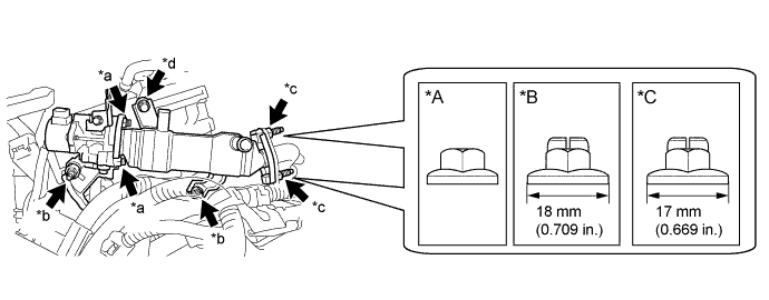
Text in Illustration *A Type A *B Type B *C Type C - - *a Nut A *b Nut B *c Nut C *d Bolt -
Tighten the 2 nuts (A).
- Torque:
- 21 N*m { 214 kgf*cm, 15 ft.*lbf }
-
Tighten the 2 nuts (B) and bolt.
- Torque:
- 21 N*m { 214 kgf*cm, 15 ft.*lbf }
Note
Make sure that all installation surfaces of the EGR valve with cooler assembly are in even contact when tightening the bolt and nuts.
-
Tighten the 2 nuts (C).
- Torque:
- Type A
- 21 N*m { 214 kgf*cm, 15 ft.*lbf }
- Type B
- 37 N*m { 377 kgf*cm, 27 ft.*lbf }
- Type C
- 26 N*m { 265 kgf*cm, 19 ft.*lbf }
-
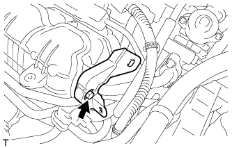
Connect the EGR valve with cooler assembly connector and engage the wire harness clamp.
-
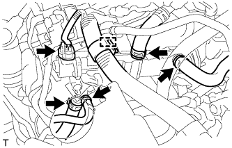
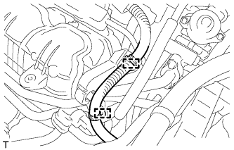
Connect the 4 water hoses to the EGR valve assembly and slide the 4 clips to secure them.
-
-
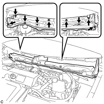
INSTALL EGR PIPE ASSEMBLY
-
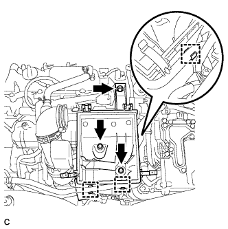
Install 2 new gaskets and EGR pipe assembly with the 4 bolts.
- Torque:
- 10 N*m { 102 kgf*cm, 7 ft.*lbf }
Note
Make sure to tighten the 4 bolts evenly until the flanges of the EGR pipe assembly contact with the installation surfaces.
-
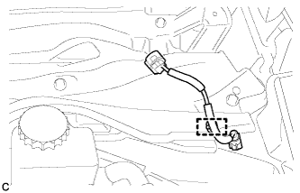
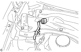
Install the wire harness support with the bolt.
- Torque:
- 10 N*m { 102 kgf*cm, 7 ft.*lbf }
-
Connect the 2 wire harness clamps.
-
-
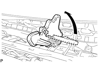
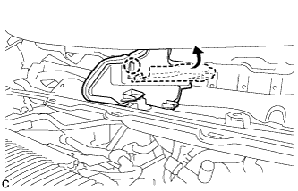
INSTALL AIR CLEANER CASE
-
Install the air cleaner case with the 3 bolts.
- Torque:
- 7.0 N*m { 71 kgf*cm, 62 in.*lbf }
-
Install the hose to the 3 clamps.
-
Install the air cleaner filter element sub-assembly.
-
-
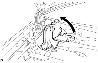
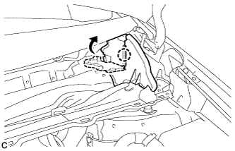
INSTALL INLET AIR CLEANER ASSEMBLY
-
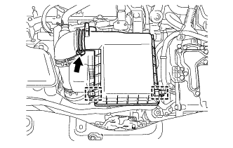
Install the inlet air cleaner assembly with the 2 bolts.
- Torque:
- 7.0 N*m { 71 kgf*cm, 62 in.*lbf }
-
-
INSTALL AIR CLEANER CAP SUB-ASSEMBLY
-
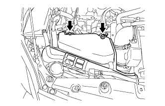
Install the air cleaner cap sub-assembly with the 2 clamps.
-
Connect the air cleaner hose assembly and tighten the hose clamp.
-
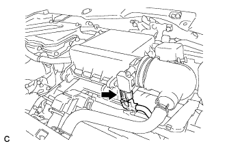
Connect the connector.
-
-
INSTALL NO. 2 CYLINDER HEAD COVER
-
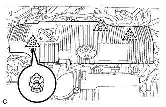
Engage the 3 clips to install the cover.
Note
-
Be sure to engage the clips securely.
-
Do not apply excessive force or hit the cover to engage the clips. This may cause the cover to break.
-
-
-
ADD COOLANT (for Engine)
-
Tighten the radiator drain cock plug.
-
Remove the reservoir tank cap.
-
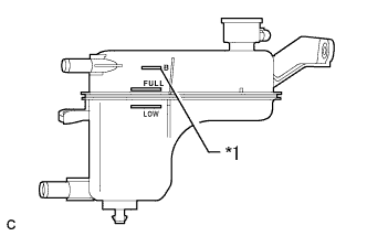
Text in Illustration *1 B Line Add coolant to B line of the reservoir tank.
Standard Capacity Item Capacity Engine coolant w/ Exhaust Heat Recirculation System:
7.2 liters (7.6 US qts, 6.3 lmp. qts)
w/o Exhaust Heat Recirculation System:
6.5 liters (6.8 US qts, 5.7 lmp. qts)
Tech Tips
TOYOTA vehicles are filled with TOYOTA SLLC at the factory. In order to avoid damage to the engine cooling system and other technical problems, only use TOYOTA SLLC or similar high quality ethylene glycol based non-silicate, non-amine, non-nitrite, non-borate coolant with long-life hybrid organic acid technology (coolant with long-life hybrid organic acid technology is a combination of low phosphates and organic acids).
Note
Never use water as a substitute for engine coolant.
-
Squeeze the inlet and outlet radiator hoses several times by hand, and then check the level of the coolant.
If the coolant level is low, add coolant.
-
Install the reservoir tank cap.
-
Put the engine in inspection mode Click here.
-
Bleed air from the cooling system.
Note
-
Before starting the engine, turn the A/C switch off.
-
Adjust the heater control to the maximum hot setting.
-
Adjust the blower speed to low setting.
-
Warm up the engine until the thermostat opens. While the thermostat is open, allow the coolant to circulate for several minutes.
Tech Tips
The thermostat opening timing can be confirmed by squeezing the inlet radiator hose by hand, and sensing vibrations when the engine coolant starts to flow inside the hose.
CAUTION:
When squeezing the radiator hose:
-
Wear protective gloves.
-
Be careful as the radiator hoses are hot.
-
Keep your hands away from the radiator fan.
-
-
Squeeze the inlet and outlet radiator hoses several times by hand to bleed air from the system.
CAUTION:
When squeezing the radiator hose:
-
Wear protective gloves.
-
Be careful as the radiator hoses are hot.
-
Keep your hands away from the radiator fan.
-
-
-
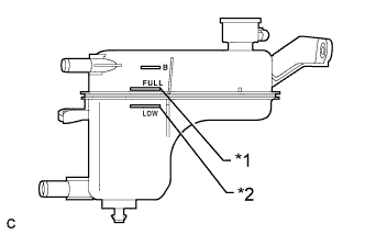
Text in Illustration *1 Full Line *2 Low Line After the engine has cooled down, check that the coolant level is between full and low.
If the coolant level is low, add coolant to the full line on the reservoir tank.
-
-
INSPECT FOR COOLANT LEAK (for Engine)
CAUTION:
Do not remove the reservoir tank cap while the engine and radiator are still hot. Pressurized, hot engine coolant and steam may be released and cause serious burns.
Note
Before performing each inspection, turn the A/C switch off.
-
Remove the reservoir tank cap.
-
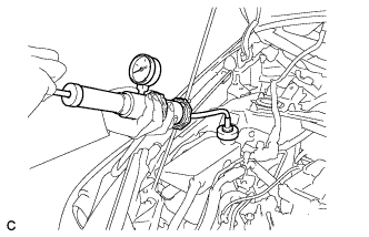
Fill the radiator and reservoir with coolant, and then attach a radiator cap tester.
-
Put the engine in inspection mode Click here.
-
Warm up the engine.
-
Using the reservoir cap tester, increase the pressure inside the radiator to 108 kPa (1.1 kgf/cm2, 16 psi), and check that the pressure does not drop. If the pressure drops, check the hoses, radiator, front exhaust pipe assembly and the heater hose around and engine water pump assembly for leaks. If no external leaks are found, check the heater core, cylinder block and cylinder head.
-
Remove the radiator cap tester.
-
Install the reservoir tank cap.
-
-
INSTALL OUTER COWL TOP PANEL SUB-ASSEMBLY (for LHD)
-
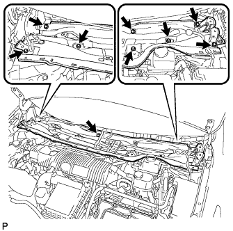
Install the outer cowl top panel sub-assembly with the 9 bolts.
- Torque:
- 12 N*m { 122 kgf*cm, 9 ft.*lbf }
-
Bend the water guard plate RH and engage the claw.
-
Bend the No. 1 heater air duct splash shield seal and engage the claw.
-
Engage the clamp to install the wire harness.
-
-
INSTALL OUTER COWL TOP PANEL SUB-ASSEMBLY (for RHD)
-
Install the outer cowl top panel with the 9 bolts.
- Torque:
- 12 N*m { 122 kgf*cm, 9 ft.*lbf }
-
Bend the water guard plate RH and engage the claw.
-
Bend the No. 1 heater air duct splash shield seal and engage the claw.
-
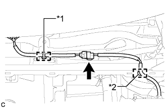
Engage the clamp*2 of the wire harness.
-
Engage the clamp*1 and connect the connector (w/ Windshield Deicer).
-
Engage the clamp of the wire harness.
-
-
INSTALL COWL BODY MOUNTING REINFORCEMENT LH (for LHD)
-
Install the cowl body mounting reinforcement LH with the 3 bolts.
- Torque:
- 12 N*m { 122 kgf*cm, 9 ft.*lbf }
-
-
INSTALL COWL BODY MOUNTING REINFORCEMENT LH (for RHD)
-
Install the cowl body mounting reinforcement LH with the 3 bolts.
- Torque:
- 12 N*m { 122 kgf*cm, 9 ft.*lbf }
-
-
INSTALL WINDSHIELD WIPER MOTOR AND LINK ASSEMBLY
-
Install the windshield wiper motor and link assembly Click here.
-