FUEL INJECTOR REMOVAL

-
PRECAUTION (w/ Navigation System for HDD)
Note
After the power switch is turned off, the navigation receiver assembly (HDD navigation system) records various types of memory and settings. As a result, after turning the power switch off, make sure to wait at least 60 seconds before disconnecting the cable from the negative (-) battery terminal.
-
DISCHARGE FUEL SYSTEM PRESSURE
-
Discharge fuel system pressure Click here.
-
-
REMOVE REAR NO. 2 FLOOR BOARD
-

Disengage the 2 guides <A> as shown in the illustration.
-
Disengage the 3 guides <B> and remove the rear No. 2 floor board.
-
-
REMOVE REAR DECK FLOOR BOX
-
Remove the rear deck floor box.
-
-
REMOVE REAR NO. 3 FLOOR BOARD
-

Disengage the 2 guides and remove the rear No. 3 floor board.
-
-
DISCONNECT CABLE FROM NEGATIVE BATTERY TERMINAL
Note
When disconnecting the cable, some systems need to be initialized after the cable is reconnected Click here.
-
REMOVE EGR WITH COOLER PIPE SUB-ASSEMBLY
Tech Tips
-
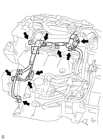
DISCONNECT ENGINE WIRE
-
Disconnect the 4 fuel injector connectors.
-
Disconnect the 4 connectors.
-
Remove the bolt.
-
Detach the 2 clamps to disconnect the wire harness.
-
-
DISCONNECT FUEL TUBE SUB-ASSEMBLY
-
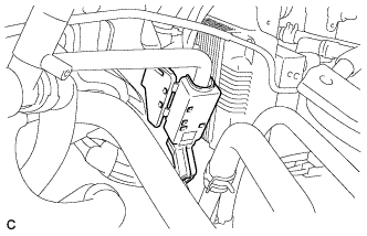
Release the claw and remove the No. 1 fuel pipe clamp.
-
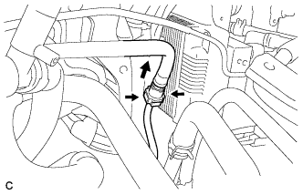
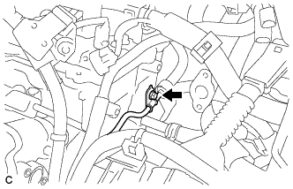
Pinch the tube connector, and then pull the tube connector off of the pipe.
Note
-
Check for foreign matter in the fuel tube around the fuel tube connector. Clean it if necessary. Foreign matter can affect the ability of the O-ring to seal the connector and fuel pipe.
-
Do not use any tools to separate the connector and pipe.
-
Do not forcefully bend, kink or twist the hose.
-
Keep the connector and pipe free from foreign matter.
-
If the connector and pipe are stuck together, pinch the connector and turn it carefully to disconnect it.
-
Put the connector in a plastic bag to prevent damage and contamination.
-
-
-
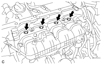
REMOVE FUEL DELIVERY PIPE SUB-ASSEMBLY
-
Remove the bolt.
-
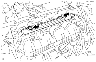
Remove the 2 bolts and the fuel delivery pipe sub-assembly.
Note
Be careful not to drop the fuel injectors when removing the fuel delivery pipe.
-
-
REMOVE NO. 1 DELIVERY PIPE SPACER
-
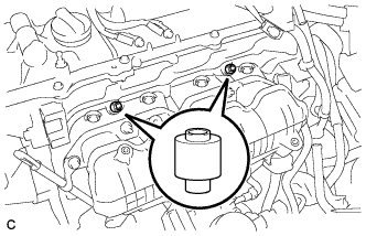
Remove the 2 delivery pipe spacers from the cylinder head.
-
-
REMOVE FUEL INJECTOR ASSEMBLY
-
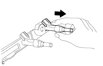
Pull the 4 fuel injector assemblies out of the fuel delivery pipe sub-assembly.
-
Remove the O-ring from each fuel injector assembly.
-
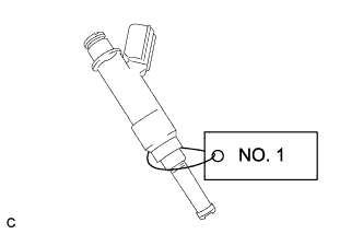
For reinstallation, attach a tag or label to each injector shaft.
Note
Prevent entry of foreign objects by covering the fuel injectors with plastic bags.
-
Remove the 4 injector vibration insulators.
-