FUEL INJECTOR REMOVAL

-
PRECAUTION (w/ Navigation System for HDD)
Note
After the power switch is turned off, the navigation receiver assembly (HDD navigation system) records various types of memory and settings. As a result, after turning the power switch off, make sure to wait at least 60 seconds before disconnecting the cable from the negative (-) auxiliary battery terminal.
-
DISCHARGE FUEL SYSTEM PRESSURE
-
REMOVE REAR NO. 2 FLOOR BOARD
-

Disengage the 2 guides <A> as shown in the illustration.
-
Disengage the 3 guides <B> and remove the rear No. 2 floor board.
-
-
REMOVE REAR DECK FLOOR BOX
-
Remove the rear deck floor box.
-
-
REMOVE REAR NO. 3 FLOOR BOARD
-

Disengage the 2 guides and remove the rear No. 3 floor board.
-
-
DISCONNECT CABLE FROM NEGATIVE AUXILIARY BATTERY TERMINAL
Note
When disconnecting the cable, some systems need to be initialized after the cable is reconnected Click here.
-
REMOVE NO. 2 CYLINDER HEAD COVER (w/o EGR System)
-
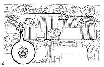
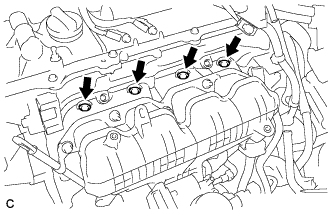
Remove the 3 clips and No. 2 cylinder head cover.
Note
-
Attempting to disengage both front and rear clips at the same time may cause the cover to break.
-
Pull the cover straight up to remove. Attempting to pull the cover forward may cause it to break.
Note
Attempting to disengage both front and rear clips at the same time may cause the cover to break.
-
-
-
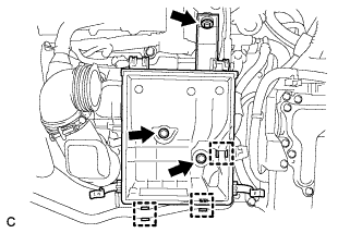
REMOVE AIR CLEANER CAP SUB-ASSEMBLY (w/o EGR System)
-
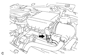
Disconnect the connector.
-
Loosen the hose clamp and disconnect the air cleaner hose assembly.
-
Remove the 2 clamps and air cleaner cap sub-assembly.
-
-
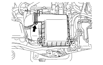
REMOVE INLET AIR CLEANER ASSEMBLY (w/o EGR System)
-
Remove the 2 bolts and inlet air cleaner assembly.
-
-
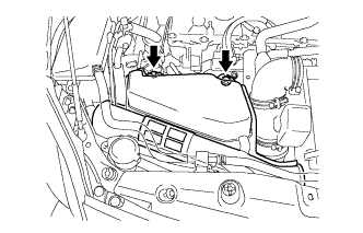
REMOVE AIR CLEANER CASE (w/o EGR System)
-
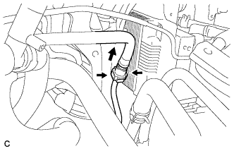
Separate the No. 4 water by-pass hose from the air cleaner case.
-
Remove the 3 bolts and air cleaner case.
-
-
REMOVE AIR CLEANER HOSE ASSEMBLY (w/o EGR System)
-
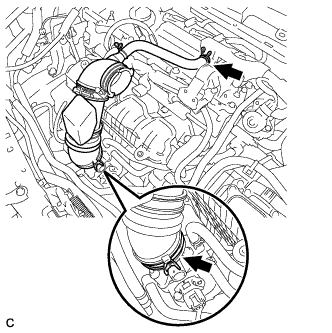
Disconnect the ventilation hose from the cylinder head cover sub-assembly.
-
Loosen the hose clamp and remove the air cleaner hose assembly.
-
-
REMOVE EGR WITH COOLER PIPE SUB-ASSEMBLY (w/ EGR System)
-
DISCONNECT ENGINE WIRE
-
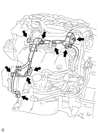
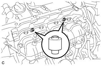
Disconnect the 4 fuel injector connectors.
-
Disconnect the 4 connectors.
-
Remove the bolt.
-
Disengage the 2 clamps to disconnect the engine wire.
-
-
DISCONNECT FUEL TUBE SUB-ASSEMBLY
-
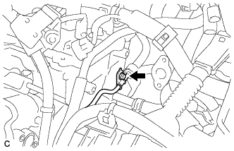
Release the claw and remove the No. 1 fuel pipe clamp.
-
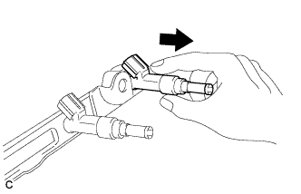
Pinch the fuel tube connector, and then pull the fuel tube connector off of the fuel pipe.
Note
-
Check for foreign matter on the fuel tube sub-assembly around the fuel tube connector. Clean it if necessary. Foreign matter can affect the ability of the O-ring to seal the fuel tube connector and fuel pipe.
-
Do not use any tools to separate the fuel tube connector and fuel pipe.
-
Do not forcibly bend, kink or twist the fuel tube sub-assembly.
-
Keep the fuel tube connector and fuel pipe free from foreign matter.
-
If the fuel tube connector and fuel pipe are stuck together, pinch the fuel tube connector and turn it carefully to disconnect it.
-
Cover the fuel tube connector with a plastic bag to prevent damage and contamination.
-
-
-
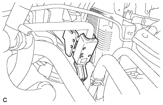
SEPARATE NO. 1 WATER BY-PASS PIPE (w/o EGR System)
-
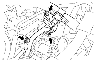
Disengage the clamp to disconnect the engine wire.
-
Remove the 2 bolts and nut, and separate the No. 1 water by-pass pipe.
-
-
REMOVE FUEL DELIVERY PIPE SUB-ASSEMBLY
-
Remove the bolt.
-
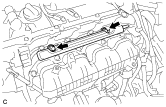
Remove the 2 bolts and the fuel delivery pipe sub-assembly with the 4 fuel injector assemblies.
Note
Be careful not to drop the fuel injector assemblies when removing the fuel delivery pipe sub-assembly.
-
-
REMOVE NO. 1 DELIVERY PIPE SPACER
-
Remove the 2 No. 1 delivery pipe spacers from the cylinder head.
-
-
REMOVE FUEL INJECTOR ASSEMBLY
-
Pull the 4 fuel injector assemblies out of the fuel delivery pipe sub-assembly.
-
Remove the O-ring from each fuel injector assembly.
-
For reinstallation, attach a tag or label with the corresponding cylinder number to each fuel injector shaft.
Note
Protect the fuel injector assemblies by covering them with plastic bags.
-
Remove the 4 injector vibration insulators.
-