ENGINE ASSEMBLY REMOVAL

-
PRECAUTION
Tech Tips
-
PRECAUTION (w/ Navigation System for HDD)
Note
After the power switch is turned off, the display and navigation module display (HDD navigation system) records various types of memory and settings. As a result, after turning the power switch off, make sure to wait at least 60 seconds before disconnecting the cable from the negative (-) auxiliary battery terminal.
-
DISCHARGE FUEL SYSTEM PRESSURE
Tech Tips
-
REMOVE REAR NO. 2 FLOOR BOARD
-

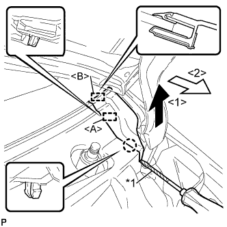
Disengage the 2 guides <A> as shown in the illustration.
-
Disengage the 3 guides <B> and remove the rear No. 2 floor board.
-
-
REMOVE REAR DECK FLOOR BOX
-
Remove the rear deck floor box.
-
-
REMOVE REAR NO. 3 FLOOR BOARD
-

Disengage the 2 guides and remove the rear No. 3 floor board.
-
-
DISCONNECT CABLE FROM AUXILIARY BATTERY NEGATIVE TERMINAL
Note
When disconnecting the cable, some systems need to be initialized after the cable is reconnected Click here.
-
REMOVE SERVICE PLUG GRIP
CAUTION:
-
Wear insulating gloves.
-
Remove the service plug grip to interrupt the high voltage circuit at the time of inspection or repair.
-
Keep the removed service plug grip in your pocket to prevent other technicians from accidentally reconnecting it while you are servicing the vehicle.
-
All the high voltage wiring connectors are colored in orange.
-
Wear insulating gloves and remove the service plug grip after sliding up the lever of the service plug grip as shown in the illustration.
CAUTION:
-
Keep the removed service plug grip in your pocket to prevent other technicians from accidentally reconnecting it while you are servicing the vehicle.
-
After removing the service plug grip, do not touch the high voltage connectors or terminals for 10 minutes.
Tech Tips
Waiting for at least 10 minutes is required to discharge the high-voltage capacitor inside the inverter with converter assembly.
-
-
-
ALIGN FRONT WHEELS FACING STRAIGHT AHEAD
-
REMOVE FRONT WHEEL
-
REMOVE REAR ENGINE UNDER COVER LH
-
REMOVE REAR ENGINE UNDER COVER RH
-
REMOVE FRONT SPOILER COVER (w/ Front Spoiler)
-
REMOVE FRONT LOWER BUMPER ABSORBER (w/ Cover)
-
REMOVE NO. 1 ENGINE UNDER COVER
-
REMOVE NO. 2 ENGINE UNDER COVER
-
DRAIN ENGINE OIL
-
Remove the oil filler cap.
-
Remove the oil pan drain plug and gasket, and drain the oil into a container.
-
Clean and install the oil pan drain plug with a new gasket.
- Torque:
- 37 N*m { 377 kgf*cm, 27 ft.*lbf }
-
-
DRAIN COOLANT (for Engine)
Note
Do not remove the reservoir tank cap, cylinder block drain cock plugs and radiator drain cock plug while the engine and radiator are still hot. Pressurized, hot engine coolant and steam may be released and cause serious burns.
-
Loosen the radiator drain cock plug and drain the coolant.
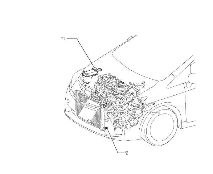
Text in Illustration *1 Reservoir Tank Cap *2 Radiator Drain Cock Plug Tech Tips
Collect the coolant in a container and dispose of it according to the local regulations.
-
-
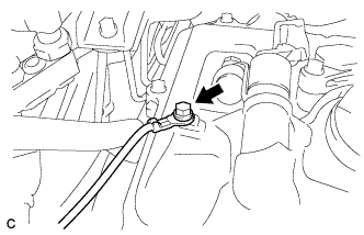
DRAIN COOLANT (for Inverter)
Note
-
Do not reuse the drained coolant because it may contain foreign objects.
-
Collect the drained coolant and measure its volume to establish a benchmark. When adding coolant, make sure to add more coolant than the measured amount.
-
Remove the reserve tank cap.
CAUTION:
To avoid the danger of being burned, do not remove the reserve tank cap while the coolant for the inverter is still hot.
-
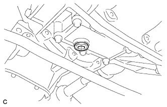
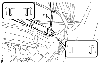
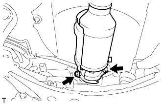
Using a hexagon wrench (10 mm), remove the drain plug indicated in the illustration and drain the coolant.
CAUTION:
Use caution when handling coolant immediately after driving or in summer because it may be hot.
-
Install the plug with a new gasket.
- Torque:
- 39 N*m { 397 kgf*cm, 29 ft.*lbf }
-
-
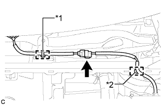
DRAIN HYBRID TRANSAXLE FLUID
-
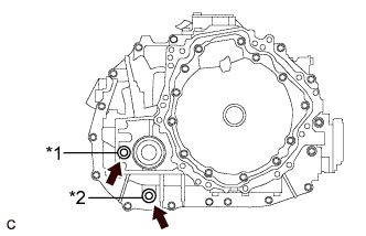
Text in Illustration *1 Filler Plug *2 Drain Plug Using a 10 mm hexagon socket wrench, remove the filler plug and gasket.
-
Using a 10 mm hexagon socket wrench, remove the drain plug and gasket.
-
Using a 10 mm hexagon socket wrench, install the drain plug and a new gasket.
- Torque:
- 50 N*m { 510 kgf*cm, 37 ft.*lbf }
-
-
REMOVE FRONT WIPER ARM HEAD CAP
-
Text in Illustration *1 Protective Tape Using a screwdriver, disengage the 3 claws to remove the front wiper arm head cap.
Tech Tips
-
Tape the screwdriver tip before use.
-
Use the same procedure for the RH side and LH side.
-
-
-
REMOVE FRONT WIPER ARM AND BLADE ASSEMBLY LH
-
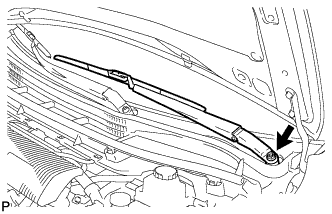
Remove the nut and the front wiper arm and blade assembly LH.
-
-
REMOVE FRONT WIPER ARM AND BLADE ASSEMBLY RH
-
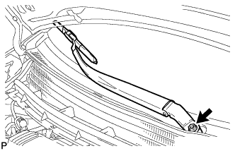
Remove the nut and the front wiper arm and blade assembly RH.
-
-
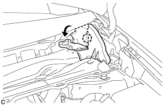
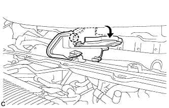
REMOVE COWL SIDE VENTILATOR SUB-ASSEMBLY LH
-
Text in Illustration *1 Protective Tape Using a screwdriver, disengage the claw and guide <A> as shown in the illustration.
Tech Tips
Tape the screwdriver tip before use.
-
Disengage the guide <B> and remove the cowl side ventilator sub-assembly LH as shown in the illustration.
-
-
REMOVE COWL SIDE VENTILATOR SUB-ASSEMBLY RH
Tech Tips
Use the same procedure as for the LH side.
-
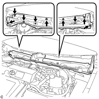
REMOVE COWL TOP VENTILATOR LOUVER SUB-ASSEMBLY (for LHD)
-
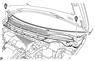
Remove the 2 clips.
-
Disengage the 5 claws and 3 guides <A>.
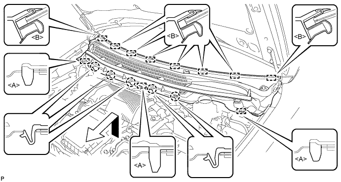
-
Disengage the 8 guides <B> and pull out the cowl top ventilator louver sub-assembly as shown in the illustration.
-
-
REMOVE COWL TOP VENTILATOR LOUVER SUB-ASSEMBLY (for RHD)
-
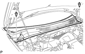
Remove the 2 clips.
-
Disengage the 6 claws and 3 guides <A>.
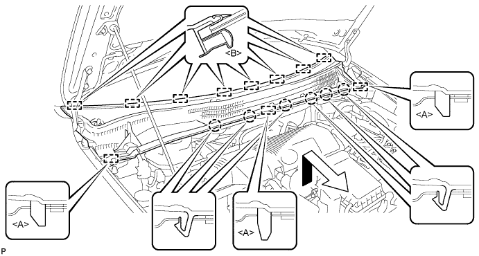
-
Disengage the 8 guides <B> and pull out the cowl top ventilator louver sub-assembly as shown in the illustration.
-
-
REMOVE WINDSHIELD WIPER MOTOR AND LINK ASSEMBLY
-
Disengage the 2 clamps.
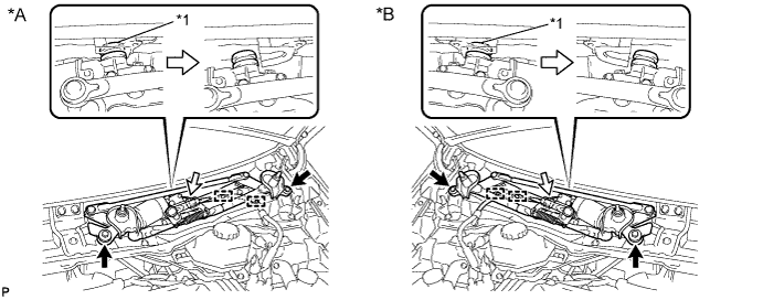
Text in Illustration *A for LHD: *B for RHD: *1 Grommet - - -
Remove the 2 bolts.
-
Disengage the grommet as shown in the illustration.
-
Disconnect the connector.
-
Remove the windshield wiper motor and link assembly.
Note
Be careful not to damage the windshield when removing the windshield wiper motor and link assembly.
-
-
REMOVE COWL BODY MOUNTING REINFORCEMENT LH (for LHD)
-
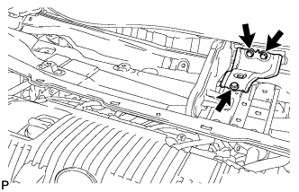
Remove the 3 bolts and cowl body mounting reinforcement LH.
-
-
REMOVE COWL BODY MOUNTING REINFORCEMENT LH (for RHD)
-
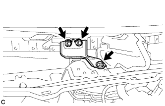
Remove the 3 bolts and cowl body mounting reinforcement LH.
-
-
REMOVE OUTER COWL TOP PANEL SUB-ASSEMBLY (for LHD)
-
Disengage the clamp and separate the wire harness.
-
Disengage the claw and bend the No. 1 heater air duct splash shield seal.
-
Disengage the claw and bend the water guard plate RH.
-
Remove the 9 bolts and outer cowl top panel sub-assembly.
-
-
REMOVE OUTER COWL TOP PANEL SUB-ASSEMBLY (for RHD)
-
Disengage the clamp and separate the wire harness from the outer cowl top panel sub-assembly.
-
Disengage the clamp*1 and disconnect the connector (w/ Windshield Deicer).
-
Disengage the clamp*2 and separate the wire harness from the outer cowl top panel sub-assembly.
-
Disengage the claw and bend the No. 1 heater air duct splash shield seal.
-
Disengage the claw and bend the water guard plate RH.
-
Remove the 9 bolts and outer cowl top panel sub-assembly.
-
-
REMOVE NO. 2 CYLINDER HEAD COVER
-
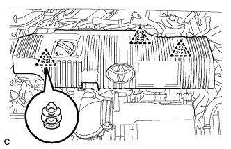
Remove the 3 clips and No. 2 cylinder head cover.
Note
-
Attempting to disengage both front and rear clips at the same time may cause the cover to break.
-
Pull the cover straight up to remove. Attempting to pull the cover forward may cause it to break.
Note
Attempting to disengage both front and rear clips at the same time may cause the cover to break.
-
-
-
REMOVE AIR CLEANER CAP SUB-ASSEMBLY
-
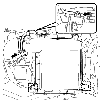
Disconnect the air flow meter connector.
-
Disconnect the 2 clamps and hose band, and remove the air cleaner cap sub-assembly.
-
Remove the air cleaner filter element.
-
-
REMOVE INLET AIR CLEANER ASSEMBLY
-
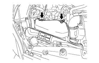
Remove the 2 bolts and inlet air cleaner assembly.
-
-
REMOVE AIR CLEANER CASE
-
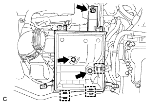
Separate the No. 4 water by-pass hose from the air cleaner case.
-
Remove the 3 bolts and air cleaner case.
-
-
REMOVE AIR CLEANER HOSE ASSEMBLY
-
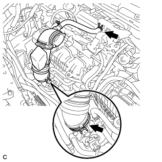
Loosen the hose clamp and separate the ventilation hose.
-
Unlock the hose clamp and remove the air cleaner hose assembly.
-
-
REMOVE RADIATOR SUPPORT OPENING COVER
-
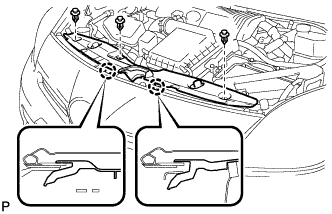
Remove the 3 clips.
-
Disengage the 2 claws and remove the radiator support opening cover.
-
-
REMOVE NO. 1 INVERTER BRACKET
-
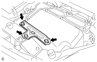
Remove the 3 bolts and No. 1 inverter bracket.
-
-
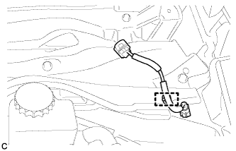
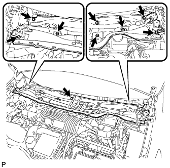
DISCONNECT ENGINE ROOM MAIN WIRE
-

Raise the lock lever and disconnect the inverter with converter connector.
-
Disconnect the engine wire from the engine room main wire.
-
Remove the bolt.
-
Remove the bolt, clamp and clip, and disconnect the engine room main ware.
-
-
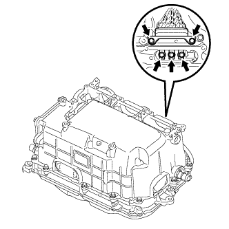
REMOVE INVERTER TERMINAL COVER
CAUTION:
Wear insulating gloves.
-
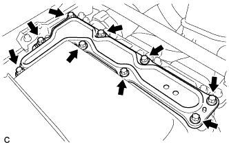
Remove the 9 bolts and inverter terminal cover.
Note
Make sure to pull the inverter terminal cover straight up, as a connector is connected to the bottom of the cover.
-
-
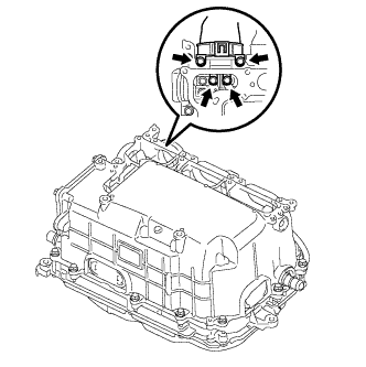
CHECK TERMINAL VOLTAGE
CAUTION:
Wear insulating gloves.
Note
Do not allow any foreign objects or water to enter the inverter with converter assembly.
-
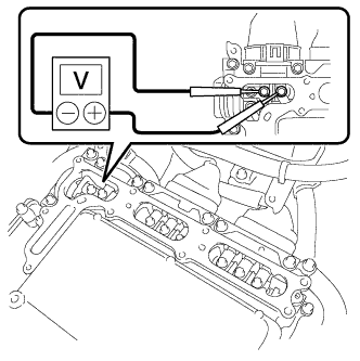
Using a voltmeter, measure the voltage between the terminals of the 2 phase connectors.
Standard voltage 0 V Tech Tips
Use measuring range of DC 750 V or more on the voltmeter.
-
-
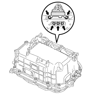
DISCONNECT FRAME WIRE
CAUTION:
Wear insulating gloves.
Note
-
Insulate the removed terminals with insulating tape.
-
Cover the hole where the cable was connected with tape or equivalent (non-residue type) to prevent entry of foreign matter.
-
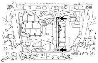
Remove the 4 bolts, and disconnect the frame wire (high voltage cables of the hybrid battery) from the inverter with converter assembly.
-
Disconnect the harness clamp.
-
-
DISCONNECT HIGH VOLTAGE CABLE OF FRONT TRANSAXLE
CAUTION:
Wear insulating gloves.
Note
-
Insulate the removed terminals with insulating tape.
-
Cover the hole where the cable was connected with tape or equivalent (non-residue type) to prevent entry of foreign matter.
-
Remove the 5 bolts, and disconnect the high voltage cables of the generator (MG1) from the inverter with converter assembly.
-
Turn back the wire harness cover and release the cable.
-
Remove the 5 bolts, and disconnect the high voltage cables of the motor (MG2) from the inverter with converter assembly.
-
Disconnect the harness clamp.
-
-
DISCONNECT NO. 2 ENGINE WIRE
-
Remove the relay block cover.
-
Release the 2 clamps, and remove the No. 1 relay block cover.
-
Remove the bolt from the No. 2 engine room wire.
-
Release the 2 claws, and disconnect the No. 2 engine room wire.
-
Connect the No. 2 engine room wire to the protector.
-
-
INSTALL INVERTER TERMINAL COVER
-
Temporarily install the inverter terminal cover with the 9 bolts to prevent any foreign objects or water from entering the inverter with converter assembly.
-
-
DISCONNECT NO. 2 ENGINE ROOM WIRE
-
Remove the relay block cover.
-
Release the 2 clamps, and remove the No. 1 relay block cover.
-
Remove the bolt from the No. 2 engine room wire.
-
Release the 2 claws, and disconnect the No. 2 engine room wire.
-
Connect the No. 2 engine room wire to the protector.
-
-
DISCONNECT WATER HOSE
-
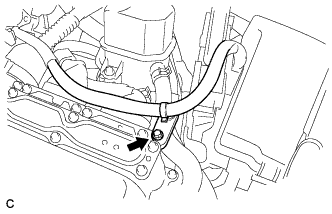
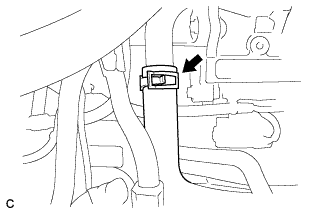
Release the retainer and disconnect the water hose from the inverter with converter assembly.
-
Release the retainer and disconnect the water hose from the inverter with converter assembly.
-
Disconnect the coolant hose from the inverter with converter assembly. Put a piece of cloth in the pipe and in the disconnected hose or cover the pipe and hose with plastic bags as shown in the illustration, so that foreign matter doesn't stick to the union or the inside of the connector and to prevent coolant from spilling near the inverter with converter assembly.
-
-
REMOVE INVERTER WITH CONVERTER ASSEMBLY
CAUTION:
Wear insulating gloves.
-
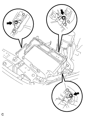
Remove the 3 bolts and inverter with converter assembly.
Note
-
Since the inverter with converter assembly is very heavy, 2 people are needed to remove the inverter with converter assembly. When removing the inverter with converter assembly, do not damage the parts around it.
-
To prevent damage, do not hold the inverter with converter assembly by the connectors.
-
To prevent damage due to static electricity, do not touch the terminals of the disconnected connectors.
-
-
-
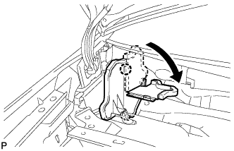
REMOVE INVERTER RESERVE TANK ASSEMBLY
-
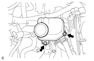
Remove the 2 bolts and inverter reserve tank assembly.
-
-
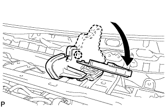
REMOVE INVERTER TRAY BRACKET
-
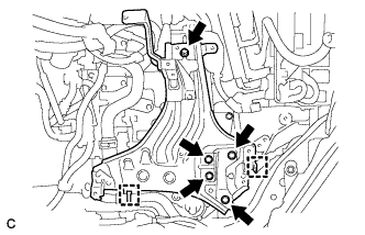
Separate the 2 clamps.
-
Remove the 5 bolts and inverter tray bracket.
-
-
DISCONNECT NO. 1 RADIATOR HOSE
-
Disconnect the No. 1 radiator hose from the radiator pipe assembly.
-
-
DISCONNECT NO. 2 RADIATOR HOSE
-
Disconnect the No. 2 radiator hose from the water inlet.
-
-
DISCONNECT NO. 4 WATER BY-PASS HOSE
-
Disconnect the No. 4 water by-pass hose from the radiator pipe assembly.
-
-
DISCONNECT NO. 3 INVERTER COOLING HOSE
-
Disconnect the No. 3 inverter cooling hose from the hybrid transaxle assembly.
-
-
DISCONNECT NO. 5 INVERTER COOLING HOSE
-
Disconnect the No. 5 inverter cooling hose from the hybrid transaxle assembly.
-
-
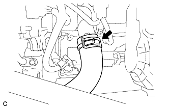
DISCONNECT OUTLET HEATER WATER HOSE
-
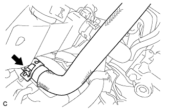
Disconnect the outlet heater water hose.
-
-
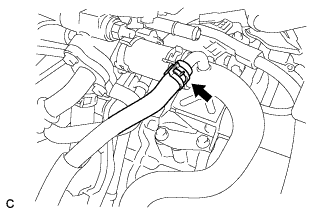
DISCONNECT INLET HEATER WATER HOSE
-
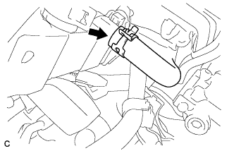
Disconnect the inlet heater water hose.
-
-
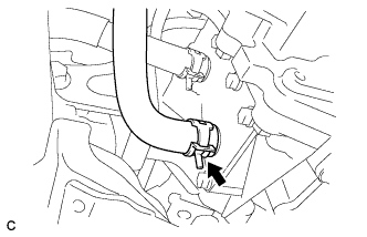
DISCONNECT HEATER HOSE
-
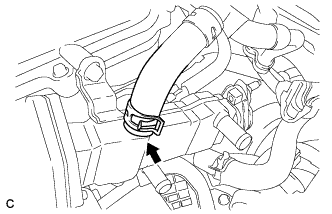
Disconnect the heater hose.
-
-
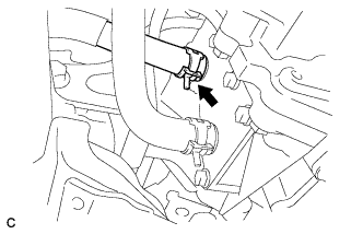
DISCONNECT NO. 1 FUEL VAPOR FEED HOSE
-
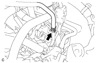
Disconnect the No. 1 fuel vapor feed hose.
-
-
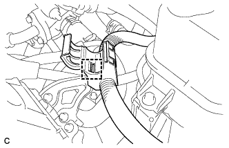
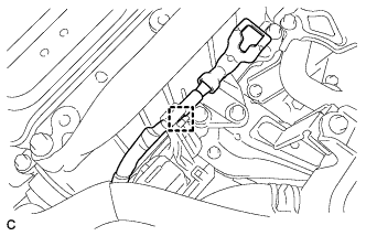
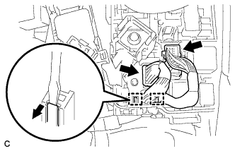
DISCONNECT FUEL TUBE SUB-ASSEMBLY
-
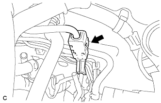
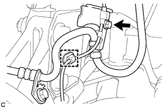
Release the claw and remove the No. 1 fuel pipe clamp.
-
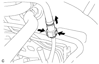
Pinch the retainer as illustrated, then pull the fuel tube connector out of the fuel pipe.
Note
-
Remove any dirt and foreign matter from the fuel tube connector before performing this work.
-
Do not allow any scratches or foreign matter on the parts when disconnecting, as the fuel tube connector has the O-rings that seal the fuel pipe.
-
Perform this work by hand. Do not use any tools.
-
Do not forcibly bend, kink or twist the nylon tube.
-
Protect the disconnected parts by covering them with plastic bags after disconnecting the fuel tube.
-
If the fuel tube connector and pipe are stuck, push and pull to release them.
-
-
-
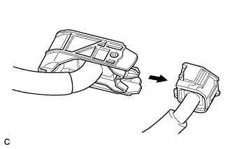
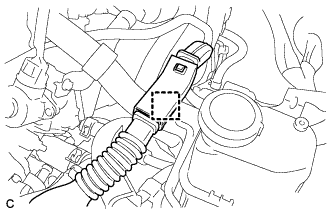
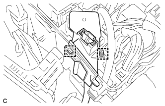
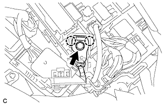
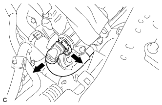
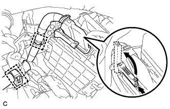
SEPARATE ELECTRIC INVERTER COMPRESSOR
-
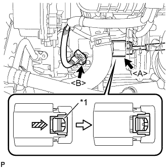
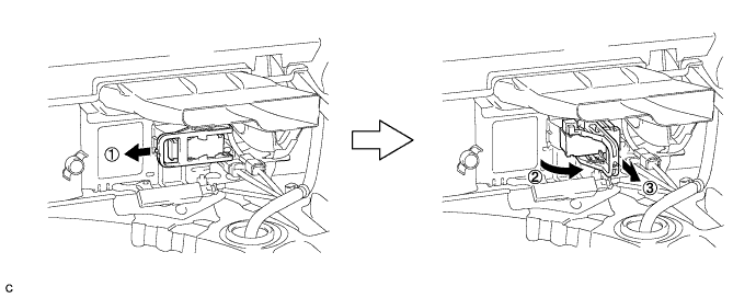
Text in Illustration *1 Green-colored Lock Using a screwdriver, slide the green-colored lock of the connector <A> in the direction indicated by the arrow in the illustration to release it and disconnect the connector.
CAUTION:
Make sure to wear insulating gloves.
Note
Insulate the removed terminals and connector with insulating tape.
-
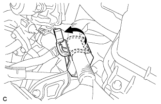
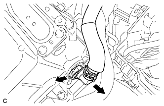
Disconnect the connector <B>.
-
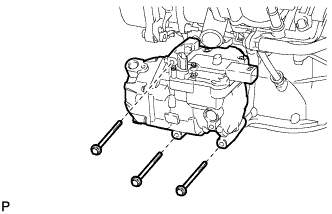
Remove the 3 bolts and electric inverter compressor.
-
-
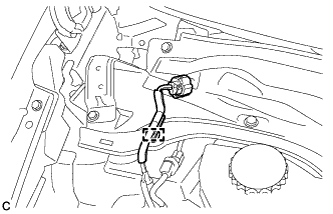
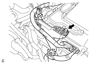
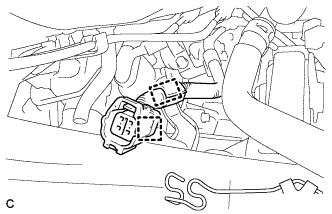
DISCONNECT WIRE HARNESS
-
Disconnect the 2 clamps.
-
Pull up the lever and disconnect the connector of the ECM.
-
Remove the 2 connectors and 2 clamps from the engine room junction block and disconnect the wire harness.
-
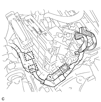
Disconnect the 3 clamps.
-
Remove the bolt and disconnect the earth wire.
-
Disconnect the 2 clamps and wire harness.
-
-
SECURE STEERING WHEEL
-
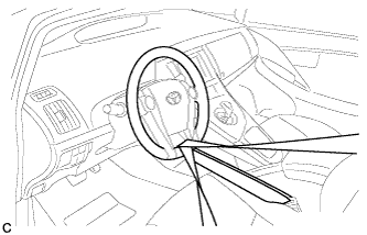
Secure the steering wheel with the seat belt in order to prevent rotation.
Tech Tips
This operation is useful to prevent damage to the spiral cable.
-
-
REMOVE COLUMN HOLE COVER SILENCER SHEET
-
Turn back the floor carpet.
-
Remove the 2 clips and column hole cover silencer sheet.
-
-
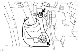
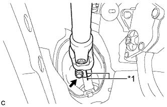
SEPARATE NO. 2 STEERING INTERMEDIATE SHAFT ASSEMBLY
-
Text in Illustration *1 Matchmark Put matchmarks on the No. 2 steering intermediate shaft assembly and steering intermediate shaft.
Note
Do not separate the No. 2 steering intermediate shaft assembly from the steering intermediate shaft.
-
Remove the bolt.
-
Separate the No. 2 steering intermediate shaft assembly from the steering intermediate shaft.
-
-
SEPARATE NO. 1 STEERING COLUMN HOLE COVER SUB-ASSEMBLY
-
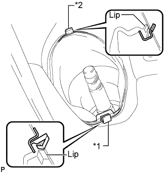
Text in Illustration *1 Clip A *2 Clip B Remove clip A, detach clip B from the body and disconnect the No. 1 steering column hole cover sub-assembly.
Note
Do not damage clips A and B.
-
-
REMOVE TAIL EXHAUST PIPE ASSEMBLY
-
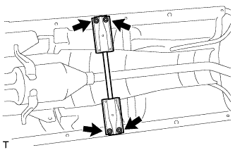
Remove the 2 bolts and 2 compression springs.
-
Remove the tail exhaust pipe assembly from the 2 exhaust pipe supports.
-
Remove the gasket from the front exhaust pipe assembly.
-
-
REMOVE FRONT NO. 3 ENGINE UNDER COVER
-
Remove the 4 clips and front No. 3 engine under cover.
-
-
REMOVE FRONT CENTER FLOOR BRACE
-
Remove the 4 bolts and front center floor brace.
-
-
REMOVE FRONT EXHAUST PIPE ASSEMBLY (w/ Exhaust Heat Recirculation System)
-
Disconnect the 2 heater water hoses.
-
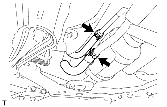
Remove the 2 bolts and 2 compression springs.
-
Remove the front exhaust pipe assembly from the 3 exhaust pipe supports.
-
Remove the gasket from the exhaust manifold.
-
-
REMOVE FRONT EXHAUST PIPE ASSEMBLY (w/o Exhaust Heat Recirculation System)
-
Remove the 2 bolts and 2 compression springs.
-
Remove the front exhaust pipe assembly from the 3 exhaust pipe supports.
-
Remove the gasket from the exhaust manifold.
-
-
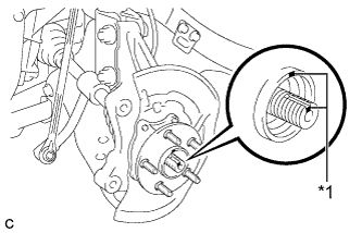
REMOVE FRONT AXLE SHAFT NUT LH
-
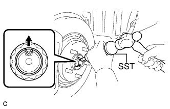
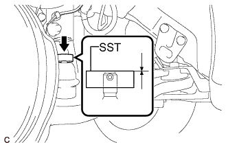
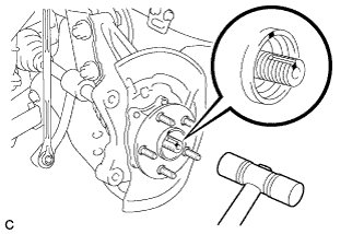
Using SST and a hammer, release the staked part of the front axle shaft nut.
- SST
- 09930-00010
Note
Loosen the staked part of the nut completely, otherwise the threads of the drive shaft may be damaged.
-
While applying the brakes, remove the front axle shaft nut.
-
-
REMOVE FRONT AXLE SHAFT NUT RH
Tech Tips
Perform the same procedure as for the LH side.
-
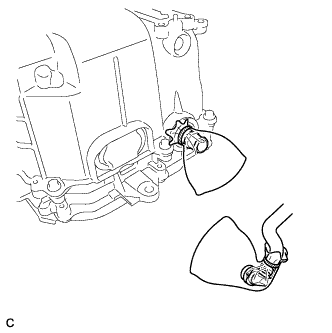
SEPARATE FRONT SPEED SENSOR LH
-
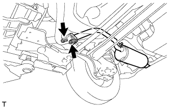
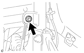
Remove the bolt and clamp, and separate the front speed sensor and front flexible hose from the front shock absorber with coil spring.
Note
Be sure to separate the front speed sensor from the front shock absorber with coil spring completely.
-
-
SEPARATE FRONT SPEED SENSOR RH
Tech Tips
Perform the same procedure as for the LH side.
-
SEPARATE TIE ROD END SUB-ASSEMBLY LH
-
Remove the clip and nut.
-
Install SST to the tie rod end.
- SST
- 09960-20010 ( 09961-02060 )
Note
Make sure that the upper ends of the tie rod end and SST are aligned.
-
Using SST, separate the tie rod end from the steering knuckle.
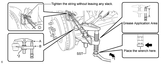
Text in Illustration *1 Turn *2 Nut - SST
- 09960-20010 ( 09961-02010 )
CAUTION:
Apply grease to the bolt threads and the tip of SST.
Note
-
Be sure to tighten the string firmly to secure SST to the steering knuckle to prevent SST from falling off.
-
Install SST with the center nut so that A and B shown in the illustration are parallel. Otherwise, the dust cover may be damaged.
-
Be sure to place the wrench on the part indicated in the illustration.
-
Do not damage the front disc brake dust cover.
-
Do not damage the ball joint dust cover.
-
Do not damage the steering knuckle.
-
-
SEPARATE TIE ROD END SUB-ASSEMBLY RH
Tech Tips
Perform the same procedure as for the LH side.
-
SEPARATE FRONT STABILIZER LINK ASSEMBLY LH
-
Remove the nut and separate the stabilizer link assembly from the front shock absorber with coil spring.
Tech Tips
If the ball joint turns together with the nut, use a hexagon wrench (6 mm) to hold the stud bolt.
-
-
SEPARATE FRONT STABILIZER LINK ASSEMBLY RH
Tech Tips
Perform the same procedure as for the LH side.
-
SEPARATE FRONT NO. 1 LOWER SUSPENSION ARM SUB-ASSEMBLY LH
-
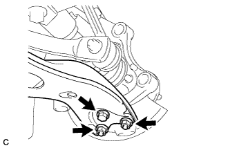
Remove the bolt and 2 nuts, and separate the front No. 1 lower suspension arm sub-assembly from the front lower ball joint.
-
-
SEPARATE FRONT NO. 1 LOWER SUSPENSION ARM SUB-ASSEMBLY RH
Tech Tips
Perform the same procedure as for the LH side.
-
SEPARATE FRONT DRIVE SHAFT ASSEMBLY LH
-
Text in Illustration *1 Matchmark Put matchmarks on the front drive shaft assembly and front axle hub sub-assembly.
-
Using a plastic hammer, separate the front drive shaft assembly from the front axle assembly. If it is difficult to separate, tap the end of the front drive shaft assembly using a brass bar and a hammer.
Note
Be careful not to damage the drive shaft boot and speed sensor rotor.
-
-
REMOVE FRONT DRIVE SHAFT ASSEMBLY LH
-
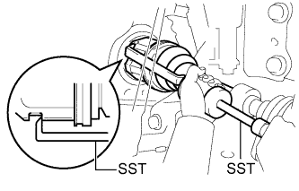
Using SST, remove the front drive shaft assembly.
- SST
- 09520-00031
- 09520-01010
- 09521-00020
Note
-
Do not damage the transaxle case oil seal.
-
Do not damage the inboard joint boot.
-
Do not drop the front drive shaft assembly.
-
-
SEPARATE FRONT DRIVE SHAFT ASSEMBLY RH
Tech Tips
Perform the same procedure as for the LH side.
-
REMOVE FRONT DRIVE SHAFT ASSEMBLY RH
Tech Tips
Perform the same procedure as for the LH side.
-
REMOVE FRONT DRIVE SHAFT HOLE SNAP RING LH
-
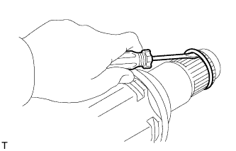
Using a screwdriver, remove the front drive shaft hole snap ring.
-
-
REMOVE FRONT DRIVE SHAFT HOLE SNAP RING RH
Tech Tips
Perform the same procedure as for the LH side.
-
REMOVE FRONT LOWER ENGINE MOUNTING BRACKET REINFORCEMENT
-
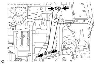
Remove the 2 bolts and front engine mounting bracket lower reinforcement.
-
-
REMOVE REAR SIDE RAIL REINFORCEMENT SUB-ASSEMBLY LH
-
Remove the 4 bolts and rear side rail reinforcement sub-assembly LH.
-
-
REMOVE REAR SIDE RAIL REINFORCEMENT SUB-ASSEMBLY RH
Tech Tips
Perform the same procedure as for the LH side.
-
REMOVE FRONT SUSPENSION MEMBER REAR BRACE LH
-
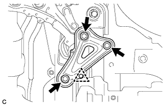
Remove the 3 bolts, clip and front suspension member rear brace LH.
-
-
REMOVE FRONT SUSPENSION MEMBER REAR BRACE RH
Tech Tips
Perform the same procedure as for the LH side.
-
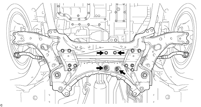
REMOVE FRONT SUSPENSION CROSSMEMBER SUB-ASSEMBLY
-
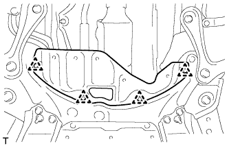
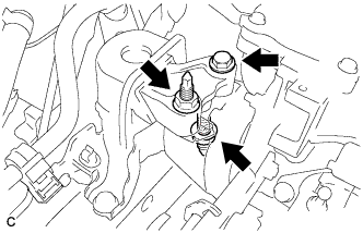
Remove the 2 bolts and 2 wire harness clamp brackets from the front suspension crossmember sub-assembly.
-
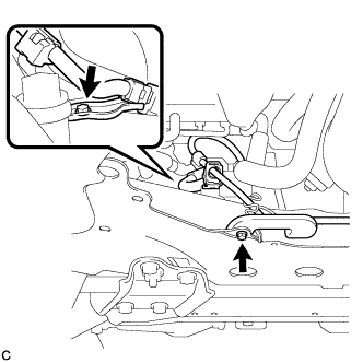
Remove the 2 bolts and 2 nuts, and separate the front suspension crossmember sub-assembly from the rear engine mounting insulator.
-
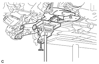
Using a transmission jack, support the front suspension crossmember sub-assembly.
-
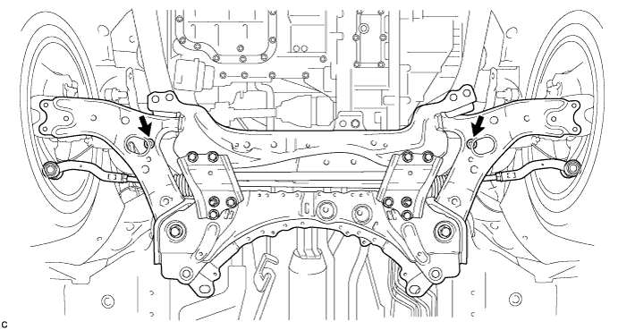
Remove the 2 bolts and front suspension crossmember sub-assembly.
-
-
REMOVE ENGINE ASSEMBLY WITH TRANSAXLE
-
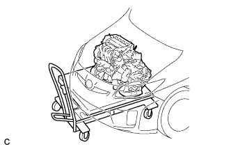
Set the engine lifter.
Note
Place the engine on wooden blocks or equivalent so that the engine is level.
-
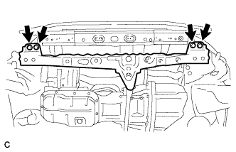
Remove the 4 bolts and front crossmember sub-assembly.
-
Remove the bolt and 2 nuts, and separate the engine mounting insulator RH.
-
Remove the bolt and nut, and separate the engine mounting insulator LH.
-
Carefully remove the engine with transaxle from the vehicle.
Note
Place the engine on wooden blocks or equivalent so that the engine is level.
-
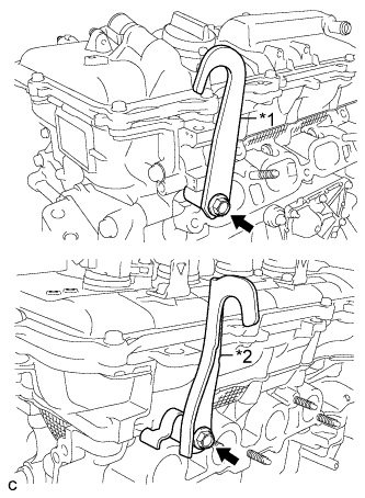
Text in Illustration *1 No. 1 engine hanger *2 No. 2 engine hanger Install the 2 engine hangers with the 2 bolts.
- Torque:
- 43 N*m { 438 kgf*cm, 32 ft.*lbf }
Part Name Part No. No. 1 engine hanger 12281-37021 No. 2 engine hanger 12282-37011 Bolt 91552-81050 -
Attach the sling device to the engine hangers and chain block.
-
-
REMOVE FRONT CROSSMEMBER SUB-ASSEMBLY
-
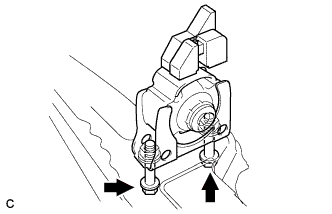
Remove the bolt and nut.
-
Remove the front engine mounting insulator from the front engine mounting bracket.
-
-
REMOVE FRONT ENGINE MOUNTING INSULATOR
-
Remove the 2 bolts and front engine mounting insulator.
-
-
REMOVE REAR ENGINE MOUNTING INSULATOR
-
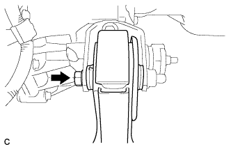
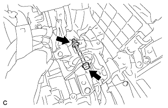
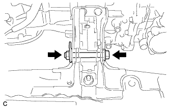
Remove the through bolt, and separate the rear engine mounting insulator.
Tech Tips
Perform this procedure only when replacement of the engine mounting insulator is necessary.
-
-
REMOVE ENGINE MOUNTING INSULATOR LH
-
Remove the 4 bolts and engine mounting insulator LH.
Tech Tips
Perform this procedure only when replacement of the engine mounting insulator is necessary.
-
-
REMOVE ENGINE MOUNTING INSULATOR SUB-ASSEMBLY RH
Tech Tips
Perform this procedure only when replacement of the engine mounting insulator is necessary.
-
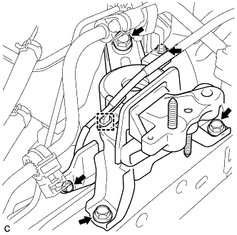
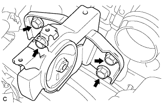
Remove the 2 bolts and separate the 2 cooler brackets.
-
Disconnect the wire harness clamp from the engine mounting insulator sub-assembly RH.
-
Remove the 3 bolts and engine mounting insulator sub-assembly RH.
-
-
REMOVE RADIATOR PIPE
-
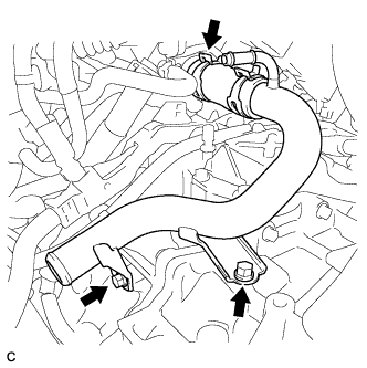
Separate the No. 3 radiator hose from the cylinder head.
-
Remove the 2 bolts and radiator pipe.
-
-
REMOVE STARTER HOLE INSULATOR
-
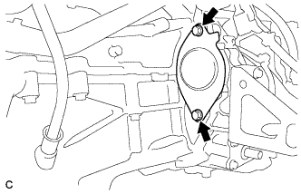
Remove the 2 bolts and starter hole insulator.
-
-
REMOVE FLYWHEEL HOUSING SIDE COVER
-
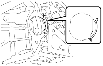
Remove the flywheel housing side cover.
-
-
REMOVE ENGINE WIRE
-
Disconnect all the wire harnesses and connectors. Make sure that no wire harnesses are connected to the engine.
-
-
REMOVE HYBRID VEHICLE TRANSAXLE ASSEMBLY
-
Remove the hybrid vehicle transaxle assembly Click here.
Note
Be careful not to apply excess force to the transmission input damper assembly when removing or installing the hybrid vehicle transaxle assembly. If excess force is applied, the transmission input damper assembly may be damaged, or its splines may become misaligned.
-
-
REMOVE TRANSMISSION INPUT DAMPER ASSEMBLY
-
Gently place the engine assembly onto wood blocks or equivalent.
Note
This step should be done while hanging the engine assembly using the engine hangers and a chain block.
-
Remove the transmission input damper assembly Click here.
-
-
REMOVE FLYWHEEL SUB-ASSEMBLY
-
Gently place the engine assembly onto wood blocks or equivalent.
Note
This step should be done while hanging the engine assembly using the engine hangers and a chain block.
-
Remove the flywheel sub-assembly Click here.
-