CAMSHAFT INSTALLATION

-
INSTALL NO. 1 CAMSHAFT BEARING
-
Clean both surfaces of the bearings.
-
Install the 2 No. 1 camshaft bearings.
-
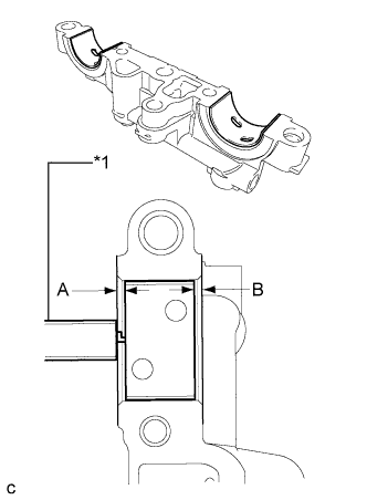
Text in Illustration *1 Vernier Caliper Using a vernier caliper, measure the distance between the bearing cap edge and the camshaft bearing edge.
Standard dimension (A - B) 0.7 mm (0.0276 in.) or less Note
Position the bearings to the center of the bearing cap by measuring dimensions A and B.
-
-
INSTALL NO. 2 CAMSHAFT BEARING
-
Clean both surfaces of the bearings.
-
Install the 2 No. 2 camshaft bearings.
-
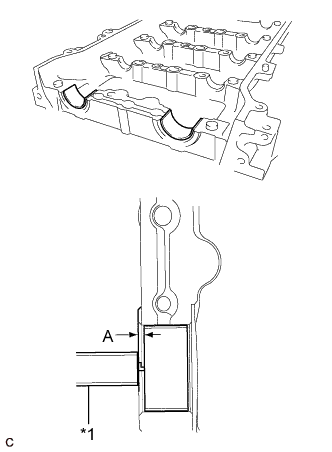
Text in Illustration *1 Vernier Caliper Using a vernier caliper, measure the distance between the bearing cap edge and the camshaft bearing edge.
Standard dimension (A) 1.05 to 1.75 mm (0.0413 to 0.0689 in.) Note
Position the bearings to the center of the bearing cap by measuring dimension A.
-
-
INSTALL NO. 2 CAMSHAFT
-
Clean the camshaft journals.
-
Apply a light coat of engine oil to the camshaft journals, camshaft housings and bearing caps.
-
Install the No. 2 camshaft to the camshaft housing.
-
-
INSTALL CAMSHAFT
-
Clean the camshaft journals.
-
Apply a light coat of engine oil to the camshaft journals, camshaft housings and bearing caps.
-
Install the camshaft to the camshaft housing.
-
-
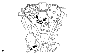
INSTALL BEARING CAP
-
Apply engine oil to the camshaft journals, camshaft housings and bearing caps.
-
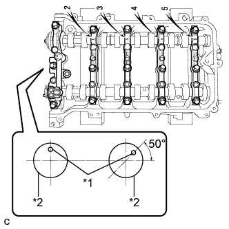
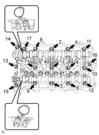
Text in Illustration *1 Knock Pin *2 Camshaft Make sure of the marks and numbers on the camshaft bearing caps and place them in each proper position and direction.
-
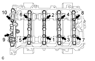
Tighten the 10 bolts in the order shown in the illustration.
- Torque:
- 16 N*m { 163 kgf*cm, 12 ft.*lbf }
-
-
INSTALL CAMSHAFT HOUSING SUB-ASSEMBLY
-
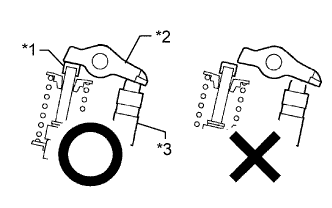
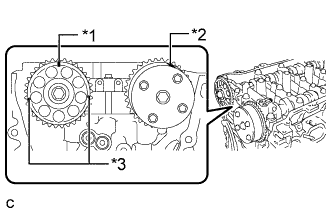
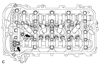
Text in Illustration *1 Valve Stem Cap *2 Valve Rocker Arm *3 Valve Lash Adjuster Check that the valve rocker arms are installed as shown in the illustration.
-
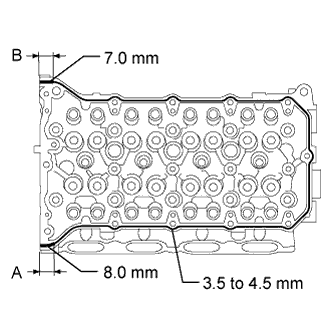
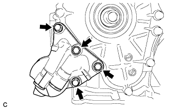
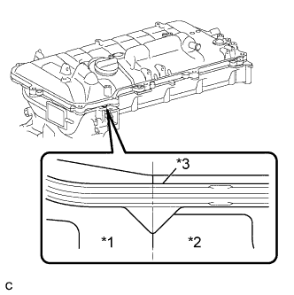
Apply seal packing in a continuous line as shown in the illustration.
Seal packing Toyota Genuine Seal Packing Black, Three Bond 1207B or equivalent Standard Seal Diameter Area Specified Condition Continuous line 3.5 to 4.5 mm (0.138 to 0.177 in.) A 8.0 mm (0.315 in.) B 7.0 mm (0.276 in.) Application Length A and B 15 mm (0.591 in.) Note
-
Remove any oil from the contact surfaces.
-
Install the camshaft housing within 3 minutes and tighten the bolts within 10 minutes of applying seal packing.
-
Do not start the engine for at least 2 hours after installation.
-
-
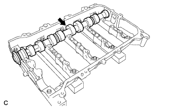
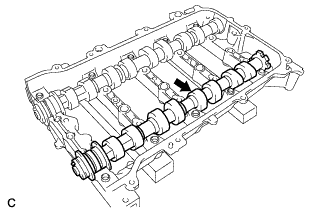
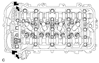
Set the camshaft and No. 2 camshaft as shown in the illustration.
-
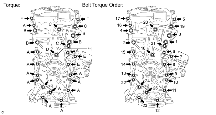
Install the camshaft housing with the 17 bolts and tighten them in the order shown in the illustration.
- Torque:
- 27 N*m { 275 kgf*cm, 20 ft.*lbf }
Note
-
After installing the camshaft housing, make sure that the cam lobes are positioned as shown in the illustration.
-
If any of the bolts is loosened during installation, remove the camshaft housing, clean the installation surfaces, and reapply seal packing.
-
If the camshaft housing is removed because any of the bolts is loosened during installation, make sure that the previously applied seal packing does not enter any oil passages.
-
After installing the camshaft housing, wipe off any seal packing that seeped out from between the housing and cylinder head.
-
-
INSTALL CAMSHAFT TIMING SPROCKET
-
Tighten the flange bolt with the camshaft timing sprocket secured in place.
- Torque:
- 54 N*m { 551 kgf*cm, 40 ft.*lbf }
-
-
INSTALL CAMSHAFT TIMING GEAR ASSEMBLY
-
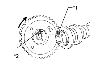
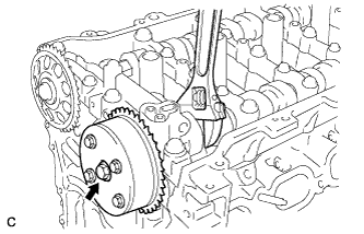
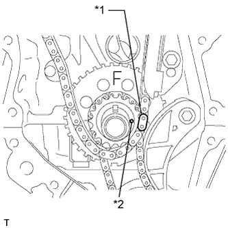
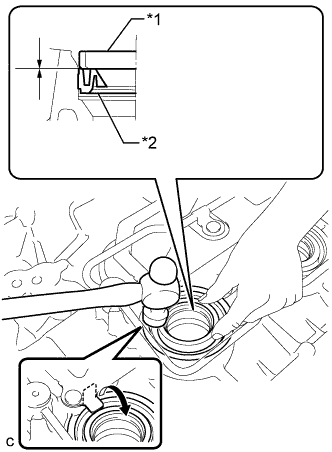
Text in Illustration *1 Straight Pin *2 Key Groove Put the camshaft timing gear and camshaft together with the straight pin and key groove misaligned as shown in the illustration.
Note
Do not forcefully push in the camshaft timing gear. This may cause the camshaft straight pin tip to damage the installation surface of the camshaft timing gear.
-
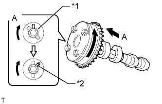
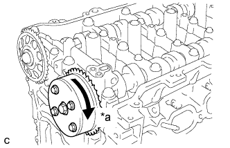
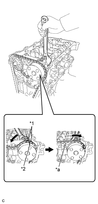
Text in Illustration *1 Straight Pin *2 Key Groove Turn the camshaft timing gear as shown in the illustration while pushing it gently against the camshaft. Push further at the position where the pin fits into the groove.
Note
Do not turn the camshaft timing gear in the retard direction (clockwise).
-
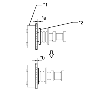
Text in Illustration *1 Camshaft Timing Gear *2 Flange *a Clearance *b No Clearance Check that there is no clearance between the camshaft timing gear and camshaft flange.
-
Tighten the flange bolt with the camshaft timing gear secured in place.
- Torque:
- 54 N*m { 551 kgf*cm, 40 ft.*lbf }
-
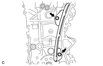
Text in Illustration *a Lock Check that the camshaft timing gear can move in the retard direction (clockwise) and is locked in the most retarded position.
-
-
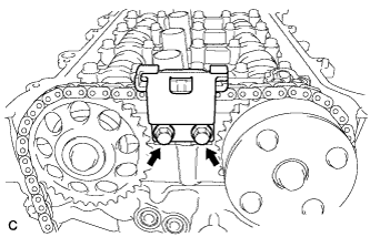
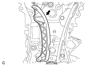
INSTALL NO. 1 CHAIN VIBRATION DAMPER
-
Install the chain vibration damper with the 2 bolts.
- Torque:
- 21 N*m { 214 kgf*cm, 15 ft.*lbf }
-
-
SET NO. 1 CYLINDER TO TDC/COMPRESSION
-
Text in Illustration *1 Timing Gear Key Temporarily install the crankshaft pulley bolt.
-
Turn the crankshaft to position the timing gear key to the top.
-
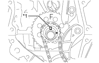
Text in Illustration *1 Timing Mark (Rectangle) *2 Timing Mark *3 Mark (Circle) Check that the timing marks on the camshaft timing gear and camshaft timing sprocket are aligned as shown in the illustration.
Tech Tips
There are 3 marks on the camshaft timing sprocket. Make sure that the timing mark (rectangle) is at the top.
-
Remove the crankshaft pulley bolt.
-
-
INSTALL CHAIN SUB-ASSEMBLY
-
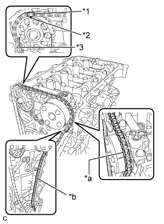
Text in Illustration *1 Mark Plate (Orange) *2 Timing Mark (Rectangle) *3 Mark (Circle) *a Place the Chain on the Sprocket *b Pass the Chain through the Damper Align the mark plate (orange) with the timing mark as shown in the illustration and install the chain.
Tech Tips
-
There are 3 marks on the camshaft timing sprocket. Make sure to align the mark plate with the timing mark (rectangle).
-
Be sure to position the mark plate at the front of the engine.
-
The mark plate on the camshaft side is colored orange.
-
Do not pass the chain around the sprocket of the camshaft timing gear. Only place it on the sprocket.
-
Pass the chain through the No. 1 vibration damper.
-
-
Place the chain on the crankshaft without passing it around the shaft.
-
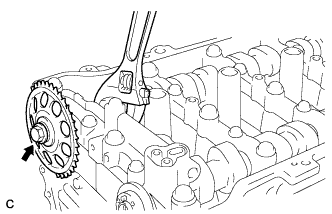
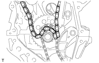
Text in Illustration *1 Mark Plate (Orange) *2 Timing Mark *a Tension the Chain Hold the hexagonal portion of the camshaft with a wrench and turn the camshaft timing gear counterclockwise to align the mark plate (orange) and timing mark, and then install the chain.
-
Hold the hexagonal portion of the camshaft with a wrench and turn the camshaft timing gear clockwise.
Tech Tips
To tension the chain, slowly turn the camshaft timing gear clockwise to prevent the chain from being misaligned.
-
Text in Illustration *1 Mark Plate (Yellow or Pink) *2 Timing Mark Align the mark plate (yellow or pink) and timing mark and install the chain to the crankshaft timing gear.
Tech Tips
The mark plate on the crankshaft side is colored pink.
-
-
CHECK NO. 1 CYLINDER TO TDC/COMPRESSION
-
Check each timing mark at TDC/compression.
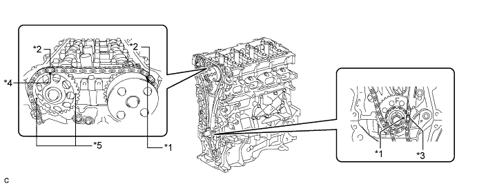
Text in Illustration *1 Timing Mark *2 Mark Plate (Orange) *3 Mark Plate (Yellow or Pink) *4 Timing Mark (Rectangle) *5 Mark (Circle) - - Tech Tips
There are 3 marks on the camshaft timing sprocket. Make sure that the timing mark (rectangle) is at the top.
-
-
INSTALL NO. 2 CHAIN VIBRATION DAMPER
-
Install the No. 2 chain vibration damper with the 2 bolts.
- Torque:
- 10 N*m { 102 kgf*cm, 7 ft.*lbf }
-
-
INSTALL CHAIN TENSIONER SLIPPER
-
Install the chain tensioner slipper to the cylinder block.
-
-
INSTALL TIMING CHAIN COVER OIL SEAL
-
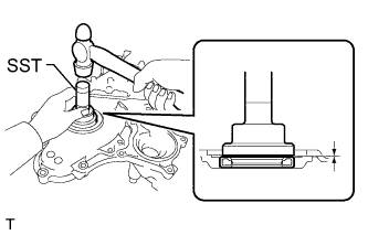
Using SST, tap in a new oil seal until its surface is flush with the timing chain cover edge.
- SST
- 09223-22010
Note
-
Keep the lip free from foreign matter.
-
Do not tap on the oil seal at an angle.
-
Make sure that the oil seal edge does not stick out of the timing chain case.
Tech Tips
Tap in the oil seal so that it is positioned within 1.0 mm from the edge of the timing chain case.
-
Apply MP grease to the lip of the oil seal.
-
-
INSTALL TIMING CHAIN COVER SUB-ASSEMBLY
-
Remove any old packing (FIPG) material and be careful not to drop any oil on the contact surfaces of the timing chain cover, cylinder head, and cylinder block.
-
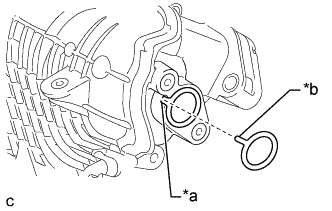
Install 3 new O-rings.
-
Apply seal packing as shown in the illustration.
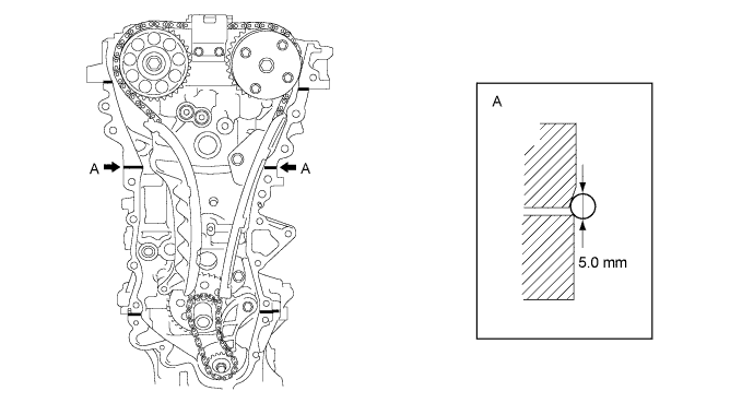
Seal packing Toyota Genuine Seal Packing Black, Three Bond 1207B or equivalent Seal diameter 5.0 mm (0.197 in.) Note
-
Remove any oil from the contact surfaces.
-
Install the chain cover within 3 minutes after applying seal packing.
-
Do not start the engine for at least 2 hours after installing the timing chain cover sub-assembly.
-
-
Apply seal packing to the timing chain cover in a line as shown in the following illustration.
Note
-
When the contact surfaces are wet, wipe them with oil-free cloth before applying seal packing.
-
Install the chain cover within 3 minutes and tighten the bolts within 15 minutes after applying seal packing.
-
Do not start the engine for at least 2 hours after installation.
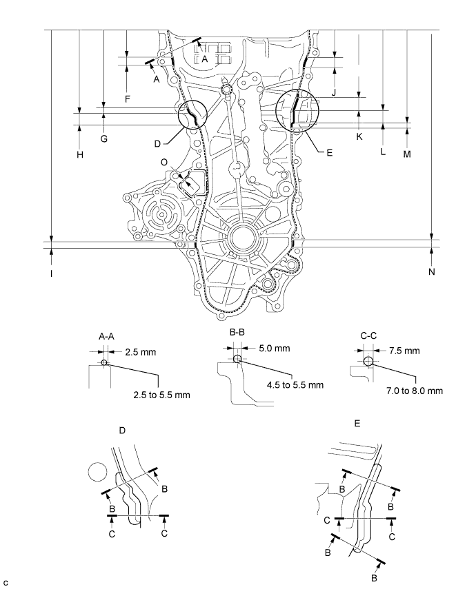
Seal Packing Item Seal Packing Dashed line Toyota Genuine Seal Packing Black, Three Bond 1207B or equivalent Continuous line Alternate long and short dashed line Toyota Genuine Seal Packing 1282B, Three Bond 1282B or equivalent Application Specification Area Seal Packing Diameter Distance from Edge of Cover to: Seal Packing Application Length Distance from Top of Cover to Top of Seal Packing Dashed line 2.5 to 3.0 mm (0.0984 to 0.118 in.) Center of seal packing
2.5 mm (0.0984 in.)
- - Continuous line 4.5 to 5.5 mm (0.177 to 0.217 in.) or 7.0 to 8.0 mm (0.276 to 0.315 in.) - - - Alternate long and short dashed line 4.0 mm (0.157 in.) Center of seal packing
3.0 mm (0.118 in.)
- - A - A 2.5 to 3.0 mm (0.0984 to 0.118 in.) Center of seal packing
2.5 mm (0.0984 in.)
- - B - B 4.5 to 5.5 mm (0.177 to 0.217 in.) Opposite edge of seal packing
5.0 mm (0.197 in.)
- - C - C 7.0 to 8.0 mm (0.276 to 0.315 in.) Opposite edge of seal packing
7.5 mm (0.295 in.)
- - F 4.5 to 5.5 mm (0.177 to 0.217 in.) - 15.5 mm (0.610 in.) 50.4 mm (1.98 in.) G 4.5 to 5.5 mm (0.177 to 0.217 in.) - 10.3 mm (0.406 in.) 143.1 mm (5.63 in.) H 7.0 to 8.0 mm (0.276 to 0.315 in.) - 19.5 mm (0.768 in.) 153.4 mm (6.04 in.) I 4.5 to 5.5 mm (0.177 to 0.217 in.) - 16.0 mm (0.630 in.) 385.8 mm (1.27 ft.) J 4.5 to 5.5 mm (0.177 to 0.217 in.) - 18.6 mm (0.732 in.) 51.4 mm (2.02 in.) K 4.5 to 5.5 mm (0.177 to 0.217 in.) - 25.3 mm (0.996 in.) 121.9 mm (4.80 in.) L 7.0 to 8.0 mm (0.276 to 0.315 in.) - 25.8 mm (1.02 in.) 147.2 mm (5.80 in.) M 4.5 to 5.5 mm (0.177 to 0.217 in.) - 5.1 mm (0.201 in.) 173.0 mm (6.81 in.) N 4.5 to 5.5 mm (0.177 to 0.217 in.) - 14.6 mm (0.575 in.) 385.8 mm (1.27 ft.) O 4.0 mm (0.157 in.) Center of seal packing
3.0 mm (0.118 in.)
- - Note
-
When the contact surfaces are wet, wipe them with oil-free cloth before applying seal packing.
-
Install the timing chain cover within 3 minutes and tighten the bolts within 10 minutes after applying seal packing.
-
After applying seal packing to the timing chain cover, install the engine mounting bracket and oil filter bracket within 10 minutes.
-
Do not add engine oil for at least 2 hours after installation.
-
-
Clean the bolt and fitting hole.
-
Install the timing chain cover.
-
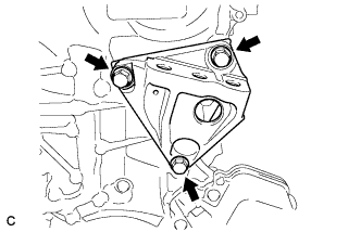
Temporarily tighten the engine mounting bracket RH with the 3 bolts.
Note
-
Install the mounting bracket within 10 minutes after installing the chain cover.
-
Do not start the engine for at least 2 hours after installation.
Bolt Length Item Length Bolt 80 mm (3.15 in.) -
-
Install 2 new O-rings.
-
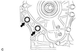
Temporarily tighten the oil filter bracket with the 4 bolts.
Note
-
Install the oil filter bracket within 10 minutes after installing the chain cover.
-
Do not start the engine for at least 2 hours after installation.
Bolt Length Item Length Bolt 35 mm (1.38 in.) -
-
Install the timing chain cover with the 25 bolts and seal washer as shown in the illustration.
Text in Illustration *1 Seal Washer - - - Torque:
- Bolt A, E, F
- 26 N*m { 260 kgf*cm, 19 ft.*lbf }
- Bolt B, C
- 51 N*m { 520 kgf*cm, 38 ft.*lbf }
- Bolt D
- 10 N*m { 102 kgf*cm, 7 ft.*lbf }
Note
-
Apply adhesive 1324 to screw part of the bolt F.
-
When the contact surfaces are wet, wipe them with oil-free cloth before applying seal packing.
-
Install the chain cover within 3 minutes and tighten the bolts within 15 minutes after applying the seal packing.
-
Do not add engine oil for at least 2 hours after installing the chain cover.
-
Do not start the engine for at least 2 hours after installing the chain cover.
Bolt Length Item Length Bolt A, F 35 mm (1.38 in.) Bolt B 55 mm (2.16 in.) Bolt C 80 mm (3.15 in.) Bolt D 40 mm (1.57 in.) Bolt E 55 mm (2.16 in.)
-
-
INSTALL CRANKSHAFT PULLEY
-
Align the pulley set key with the key groove of the pulley.
-
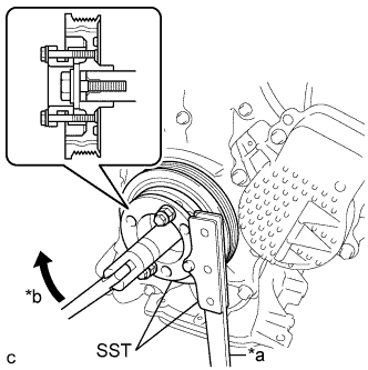
Text in Illustration *a Hold *b Turn Using SST, hold the pulley in place and tighten the bolt.
- SST
- 09213-58014 ( 91551-80840 )
- 09330-00021
- Torque:
- 190 N*m { 1937 kgf*cm, 140 ft.*lbf }
-
-
INSTALL NO. 1 CHAIN TENSIONER ASSEMBLY
-
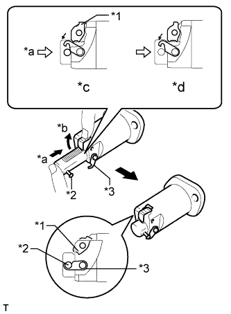
Text in Illustration *1 Cam *2 Pin *3 Hook *a Push *b Raise *c CORRECT *d INCORRECT Release the cam, and then fully push in the plunger and engage the hook to the pin so that the plunger is in the position shown in the illustration.
Note
Make sure that the cam engages the first tooth of the plunger to allow the hook to pass over the pin.
-
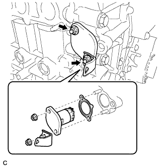
Install a new gasket, the bracket and chain tensioner with the 2 nuts.
- Torque:
- 12 N*m { 122 kgf*cm, 9 ft.*lbf }
Note
If the hook releases the plunger while the chain tensioner is being installed, set the hook again.
-
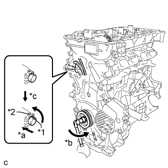
Text in Illustration *1 Pin *2 Hook *a Push *b Turn *c Disconnect Rotate the crankshaft counterclockwise slightly and check that the hook becomes released.
-
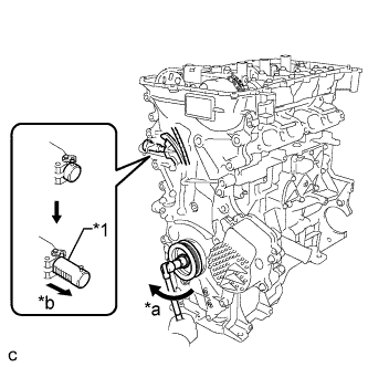
Text in Illustration *1 Plunger *a Turn *b Plunger Extended Turn the crankshaft clockwise and check that the plunger is extended.
-
-
INSTALL SPARK PLUG TUBE GASKET
-
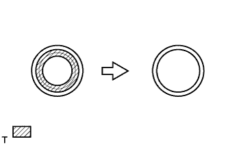
Using a cutter knife, cut off the seal part of the removed gasket.
Text in Illustration 
Part to Cut Off -
Text in Illustration *1 Plug Tube Gasket without Sealing Part *2 New Plug Tube Gasket Using a hammer and the plug tube gasket which has had the sealing part cut off, uniformly tap in a new plug tube gasket all the way.
Note
-
Keep the lip free of foreign matter.
-
Do not tap in the plug tube gasket.
Tech Tips
If a plug tube gasket that will be used to install a new gasket is deformed, and cannot be positioned on a new gasket, correct the deformation using pliers.
-
-
Return the claws of the ventilation baffle plate to their original positions.
-
-
INSTALL CYLINDER HEAD COVER GASKET
-
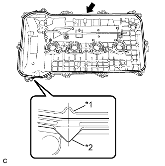
Text in Illustration *1 Cylinder Head Cover *2 Cylinder Head Cover Gasket Install a new cylinder head cover gasket to the cylinder head cover.
Note
-
Remove any oil from the contact surfaces.
-
Misalignment between the center of the cylinder head cover rib and the center of the cylinder head gasket tab is within 4 mm (0.157 in.).
-
-
-
INSTALL CYLINDER HEAD COVER SUB-ASSEMBLY
-
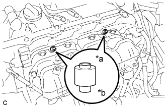
Install 2 new gaskets to the camshaft bearing cap.
-
Apply seal packing as shown the illustration.
Seal packing Toyota Genuine Seal Packing Black, Three Bond 1207B or equivalent Standard diameter 4.0 mm (0.157 in.) Note
-
Remove any oil from the contact surfaces.
-
Install the cylinder head cover sub-assembly within 3 minutes and tighten the bolts within 15 minutes of applying seal packing.
-
Do not start the engine for at least 2 hours after the installation.
-
-
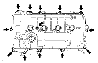
Text in Illustration *1 Timing Chain Cover *2 Camshaft Housing *3 Cylinder Head Cover Gasket Install the cylinder head cover with a new seal washer and the 13 bolts.
- Torque:
- 10 N*m { 102 kgf*cm, 7 ft.*lbf }
Note
Misalignment between the contact surfaces of the timing chain cover and the camshaft housing and the center of the cylinder head gasket tab is within 4 mm (0.157 in.).
-
-
INSTALL IGNITION COIL ASSEMBLY
-
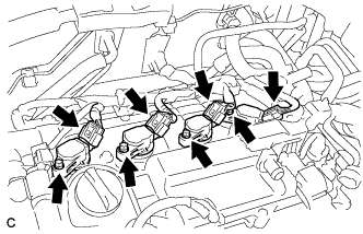
Install the 4 ignition coils with the 4 bolts.
- Torque:
- 10 N*m { 102 kgf*cm, 7 ft.*lbf }
Note
When installing each ignition coil, do not damage the plug cap on the engine head cover opening or the upper edge of the spark plug tube.
-
Connect the 4 ignition coil connectors.
-
-
INSTALL FUEL INJECTOR ASSEMBLY
-
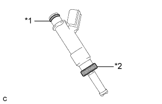
Text in Illustration *1 O-ring *2 Injector Vibration Insulator Install a new injector vibration insulator and O-ring to each fuel injector assembly.
-
Apply a light coat of gasoline or spindle oil to the contact surfaces of the new O-ring on each fuel injector assembly.
-
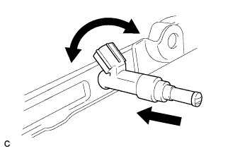
While turning the fuel injector assembly left and right, install it onto the fuel delivery pipe sub-assembly.
Note
-
Do not damage the fuel injector assembly or O-ring.
-
Do not twist the O-ring.
-
After installing each fuel injector assembly, check that it turns smoothly. If not, replace the O-ring with a new one.
-
-
-
INSTALL NO. 1 DELIVERY PIPE SPACER
-
Text in Illustration *a Delivery Pipe Side *b Cylinder Head Side Install the 2 No. 1 delivery pipe spacers onto the cylinder head.
Note
Install the No. 1 delivery pipe spacers in the correct direction.
-
-
INSTALL FUEL DELIVERY PIPE SUB-ASSEMBLY
-
Install the fuel delivery pipe sub-assembly with the 4 fuel injector assemblies and install the 2 bolts.
- Torque:
- 21 N*m { 214 kgf*cm, 15 ft.*lbf }
Note
-
Be careful not to drop the fuel injector assemblies when installing the fuel delivery pipe sub-assembly.
-
Check that the fuel injector assemblies rotate smoothly after installing the fuel delivery pipe sub-assembly.
-
Install the bolt to secure the fuel delivery pipe sub-assembly.
- Torque:
- 21 N*m { 214 kgf*cm, 15 ft.*lbf }
-
-
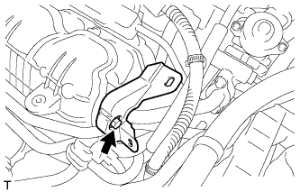
INSTALL FUEL VAPOR FEED PIPE
-
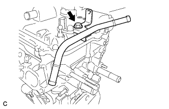
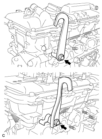
Install the fuel vapor feed pipe with the bolt.
- Torque:
- 43 N*m { 438 kgf*cm, 32 ft.*lbf }
-
-
INSTALL INTAKE MANIFOLD
-
w/ Stud Bolt:
-
Using an E6 "TORX" socket wrench, install the 2 stud bolts to the intake manifold.
- Torque:
- 5.0 N*m { 51 kgf*cm, 44 in.*lbf }
Tech Tips
If a stud bolt is deformed or the threads are damaged, replace the stud bolt.
-
-
Install a new No. 1 intake manifold to head gasket to the intake manifold.
-
Install the intake manifold with the 2 bolts and 2 nuts.
- Torque:
- 28 N*m { 286 kgf*cm, 21 ft.*lbf }
-
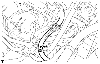
Connect the fuel vapor feed hose and ventilation hose to the intake manifold.
-
Install a new O-ring to the engine oil level dipstick guide sub-assembly.
-
Apply a light coat of engine oil to the O-ring.
-
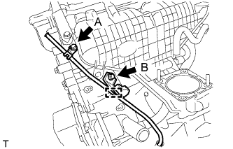
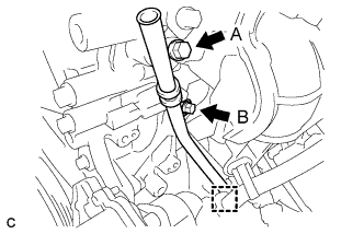
Install the engine oil level dipstick guide sub-assembly with the 2 bolts and connect the wire harness clamp.
- Torque:
- Bolt (A)
- 28 N*m { 286 kgf*cm, 21 ft.*lbf }
- Bolt (B)
- 21 N*m { 214 kgf*cm, 15 ft.*lbf }
-
Install the engine oil level dipstick.
-
Connect the 2 wire harness clamps and 3 connectors.
-
w/o EGR System:
-
Text in Illustration *a Groove *b Protrusion Install a new gasket to the intake manifold.
Tech Tips
Align the protrusion of the gasket with the groove on the intake manifold.
-
Install the surge tank cover to the intake manifold with the 2 bolts.
- Torque:
- 10 N*m { 102 kgf*cm, 7 ft.*lbf }
-
Install the wire harness support to the surge tank cover with the bolt.
- Torque:
- 10 N*m { 102 kgf*cm, 7 ft.*lbf }
-
Connect the 2 wire harness clamps.
-
-
-
INSTALL NO. 1 WATER BY-PASS PIPE (w/o EGR System)
-
Using an E8 "TORX" socket wrench, install the stud bolt to the cylinder head sub-assembly .
- Torque:
- 9.5 N*m { 97 kgf*cm, 84 in.*lbf }
-
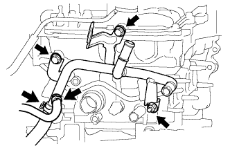
Install the No. 1 water by-pass pipe to the cylinder head sub-assembly with the 2 bolts and nut.
- Torque:
- 21 N*m { 214 kgf*cm, 15 ft.*lbf }
-
Connect the 2 water hoses to the No. 1 water by-pass pipe.
-
-
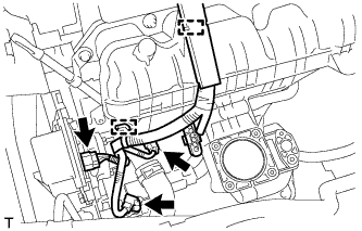
INSTALL EGR COOLER SUB-ASSEMBLY (w/ EGR System)
-
Temporarily install a new gasket and EGR valve assembly to the EGR with cooler pipe sub-assembly with the 2 nuts.
-
Install a new gasket and set the EGR valve with cooler assembly in place.
-
Using an E8 "TORX" socket wrench, install the 4 stud bolts.
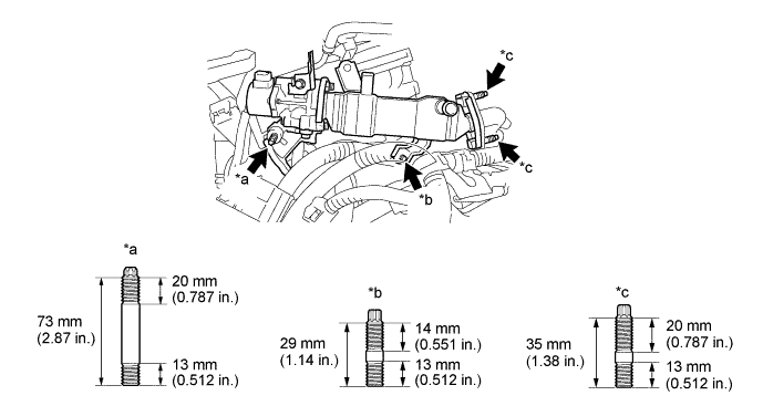
Text in Illustration *a Stud Bolt A *b Stud Bolt B *c Stud Bolt C - - - Torque:
- Stud bolt A and stud bolt B
- 9.5 N*m { 97 kgf*cm, 84 in.*lbf }
- Stud bolt C
- 5.0 N*m { 51 kgf*cm, 44 in.*lbf }
If a stud bolt is deformed or the threads are damaged, replace it.
-
Temporarily install the 2 nuts (B), 2 nuts (C) and bolt.
Tech Tips
The type B and type C of the nut (C) are non-reusable.
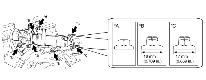
Text in Illustration *A Type A *B Type B *C Type C - - *a Nut A *b Nut B *c Nut C *d Bolt -
Tighten the 2 nuts (A).
- Torque:
- 21 N*m { 214 kgf*cm, 15 ft.*lbf }
-
Tighten the 2 nuts (B) and bolt.
- Torque:
- 21 N*m { 214 kgf*cm, 15 ft.*lbf }
Note
Make sure that all installation surfaces of the EGR valve with cooler assembly are in even contact when tightening the bolt and nuts.
-
Tighten the 2 nuts (C).
- Torque:
- Type A
- 21 N*m { 214 kgf*cm, 15 ft.*lbf }
- Type B
- 37 N*m { 377 kgf*cm, 27 ft.*lbf }
- Type C
- 26 N*m { 265 kgf*cm, 19 ft.*lbf }
-
Connect the EGR valve with cooler assembly connector and engage the wire harness clamp.
-
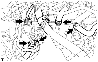
Connect the 4 water hoses to the EGR valve assembly and slide the 4 clips to secure them.
-
-
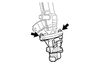
INSTALL EGR VALVE ASSEMBLY (w/ EGR System)
-
Temporarily install a new gasket and EGR valve assembly to the EGR with cooler pipe sub-assembly with the 2 nuts.
-
Install a new gasket and set the EGR valve with cooler assembly in place.
-
Using an E8 "TORX" socket wrench, install the 4 stud bolts.
Text in Illustration *a Stud Bolt A *b Stud Bolt B *c Stud Bolt C - - - Torque:
- Stud bolt A and stud bolt B
- 9.5 N*m { 97 kgf*cm, 84 in.*lbf }
- Stud bolt C
- 5.0 N*m { 51 kgf*cm, 44 in.*lbf }
If a stud bolt is deformed or the threads are damaged, replace it.
-
Temporarily install the 2 nuts (B), 2 nuts (C) and bolt.
Tech Tips
The type B and type C of the nut (C) are non-reusable.
Text in Illustration *A Type A *B Type B *C Type C - - *a Nut A *b Nut B *c Nut C *d Bolt -
Tighten the 2 nuts (A).
- Torque:
- 21 N*m { 214 kgf*cm, 15 ft.*lbf }
-
Tighten the 2 nuts (B) and bolt.
- Torque:
- 21 N*m { 214 kgf*cm, 15 ft.*lbf }
Note
Make sure that all installation surfaces of the EGR valve with cooler assembly are in even contact when tightening the bolt and nuts.
-
Tighten the 2 nuts (C).
- Torque:
- Type A
- 21 N*m { 214 kgf*cm, 15 ft.*lbf }
- Type B
- 37 N*m { 377 kgf*cm, 27 ft.*lbf }
- Type C
- 26 N*m { 265 kgf*cm, 19 ft.*lbf }
-
Connect the EGR valve with cooler assembly connector and engage the wire harness clamp.
-
Connect the 4 water hoses to the EGR valve assembly and slide the 4 clips to secure them.
-
-
INSTALL EGR PIPE ASSEMBLY (w/ EGR System)
-
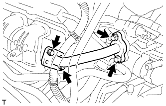
Install 2 new gaskets and EGR pipe assembly with the 4 bolts.
- Torque:
- 10 N*m { 102 kgf*cm, 7 ft.*lbf }
Note
Make sure to tighten the 4 bolts evenly until the flanges of the EGR pipe assembly contact with the installation surfaces.
-
Install the wire harness support with the bolt.
- Torque:
- 10 N*m { 102 kgf*cm, 7 ft.*lbf }
-
Connect the 2 wire harness clamps.
-
-
INSTALL ENGINE OIL LEVEL DIPSTICK GUIDE
-
Apply a light coat of engine oil to a new O-ring.
-
Install the O-ring to the engine oil level dipstick guide.
-
Install the engine oil level dipstick guide with the 2 bolts.
- Torque:
- Bolt A
- 28 N*m { 286 kgf*cm, 21 ft.*lbf }
- Bolt B
- 21 N*m { 214 kgf*cm, 15 ft.*lbf }
-
Connect the clamp to the engine oil level dipstick guide.
-
Install the engine oil level dipstick.
-
-
INSTALL THROTTLE BODY ASSEMBLY
-
Type A:
-
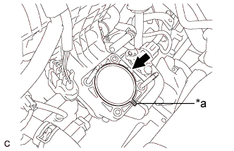
Text in Illustration *a Protrusion Install a new gasket onto the intake manifold.
Tech Tips
Orient the protrusion of the gasket as shown in the illustration.
-
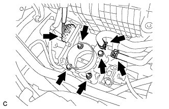
Install the throttle body assembly with the 2 bolts and 2 nuts.
- Torque:
- 10 N*m { 102 kgf*cm, 7 ft.*lbf }
-
Connect the No. 2 water by-pass hose.
-
Connect the No. 1 water by-pass hose and connector.
-
-
Type B:
-
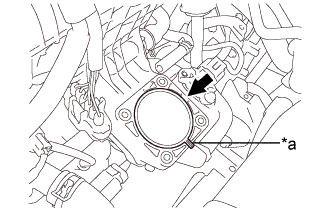
Text in Illustration *a Protrusion Install a new gasket onto the intake manifold.
Tech Tips
Orient the protrusion of the gasket as shown in the illustration.
-
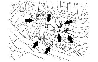
Install the throttle body assembly with the 4 bolts.
- Torque:
- 10 N*m { 102 kgf*cm, 7 ft.*lbf }
-
Connect the No. 2 water by-pass hose.
-
Connect the No. 1 water by-pass hose and connector.
-
-
-
INSTALL ENGINE HANGERS
-
Install the 2 engine hangers with the 2 bolts.
- Torque:
- 43 N*m { 438 kgf*cm, 32 ft.*lbf }
Part Name Part No. No. 1 engine hanger 12281-37021 No. 2 engine hanger 12282-37011 Bolt 91552-81050
-
-
REMOVE ENGINE FROM ENGINE STAND
-
Remove the bolts and engine from the engine stand.
-
-
INSTALL ENGINE ASSEMBLY WITH TRANSAXLE
-
Install the engine assembly with transaxle Click here.
-