ENGINE ASSEMBLY INSTALLATION

-
INSTALL FLYWHEEL SUB-ASSEMBLY
-
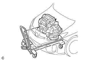
Gently place the engine assembly onto wood blocks or equivalent.
Note
This step should be done while hanging the engine assembly using the engine hangers and a chain block.
-
Install the flywheel sub-assembly Click here.
-
-
INSTALL TRANSMISSION INPUT DAMPER ASSEMBLY
-
Gently place the engine assembly onto wood blocks or equivalent.
Note
This step should be done while hanging the engine assembly using the engine hangers and a chain block.
-
Install the transmission input damper assembly Click here.
-
-
INSTALL HYBRID VEHICLE TRANSAXLE ASSEMBLY
-
Install the hybrid vehicle transaxle assembly Click here.
Note
Be careful not to apply excess force to the transmission input damper assembly when removing or installing the hybrid vehicle transaxle assembly. If excess force is applied, the transmission input damper assembly may be damaged, or its splines may become misaligned.
-
-
INSTALL ENGINE WIRE
-
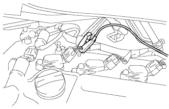
Install the engine wire to the engine.
-
-
INSTALL FLYWHEEL HOUSING SIDE COVER
-
Install the flywheel housing side cover.
-
-
INSTALL STARTER HOLE INSULATOR
-
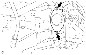
Install the starter hole insulator with the 2 bolts.
- Torque:
- 37 N*m { 377 kgf*cm, 27 ft.*lbf }
-
-
INSTALL RADIATOR PIPE
-
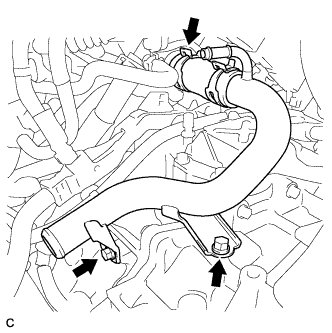
Install the radiator pipe with the 2 bolts.
- Torque:
- 19 N*m { 194 kgf*cm, 14 ft.*lbf }
-
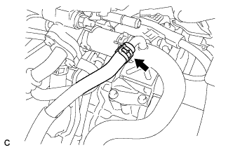
Install the No. 3 radiator hose with the clamp.
-
-
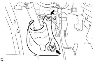
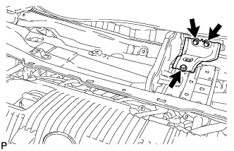
INSTALL ENGINE MOUNTING INSULATOR SUB-ASSEMBLY RH
Tech Tips
Perform this procedure only when replacement of the engine mounting insulator is necessary.
-
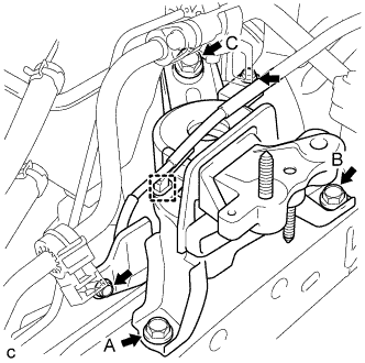
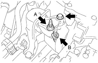
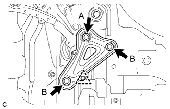
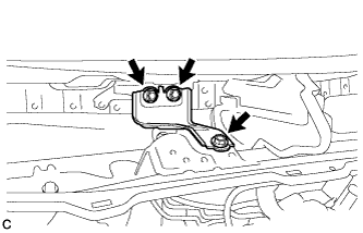
Position the engine mounting insulator sub-assembly RH as shown in the illustration.
-
Temporarily install bolt A to the engine mounting insulator sub-assembly RH.
-
Tighten the 3 bolts to the engine mounting insulator sub-assembly RH in the order the bolt B, bolt C and bolt A.
- Torque:
- 95 N*m { 969 kgf*cm, 70 ft.*lbf }
-
Connect the wire harness clamp to the engine mounting insulator sub-assembly RH.
-
Install the 2 cooler brackets with the 2 bolts.
- Torque:
- 9.8 N*m { 100 kgf*cm, 87 in.*lbf }
-
-
INSTALL ENGINE MOUNTING INSULATOR LH
Tech Tips
Perform this procedure only when replacement of the engine mounting insulator is necessary.
-
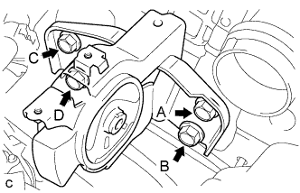
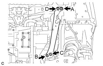
Temporarily install bolt A to the engine mounting insulator LH.
-
Tighten the 4 bolts to the engine mounting insulator LH in the order the bolt C, bolt B, bolt D and bolt A.
- Torque:
- 95 N*m { 969 kgf*cm, 70 ft.*lbf }
-
-
INSTALL REAR ENGINE MOUNTING INSULATOR
-
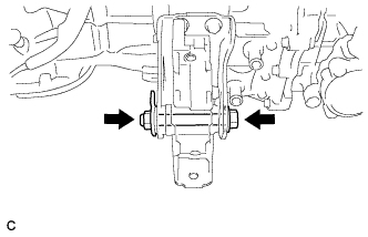
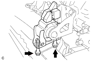
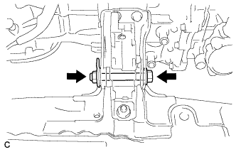
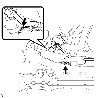
Install the rear engine mounting insulator to the engine mounting bracket with the through bolt.
- Torque:
- 95 N*m { 969 kgf*cm, 70 ft.*lbf }
Tech Tips
Perform this procedure only when replacement of the engine mounting insulator is necessary.
-
-
INSTALL FRONT ENGINE MOUNTING INSULATOR
-
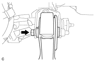
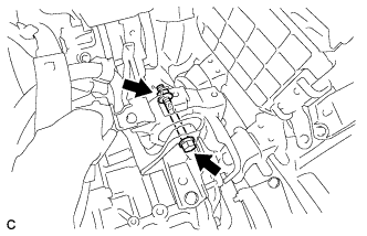
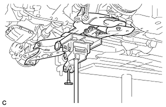
Temporarily install the front engine mounting insulator with the bolt and nut.
-
-
INSTALL ENGINE ASSEMBLY WITH TRANSAXLE
-
Set the engine assembly with transaxle on the engine lifter.
Note
-
Install a height adjustment attachment and plate lift attachment onto the engine assembly with transaxle.
-
Do not position a height adjustment attachment or plate lift attachment onto the front frame assembly.
Tech Tips
Place the engine on wooden blocks or equivalents so that the engine is level.
-
-
Remove the 2 bolts and 2 engine hangers.
-
Set the engine assembly with transaxle and front suspension crossmember on the engine lifter.
-
Operate the engine lifter and lift the engine assembly with transaxle and front suspension crossmember to the position where the engine mounting insulators RH and LH can be installed.
CAUTION:
Do not raise the engine more than necessary. If the engine is raised excessively, the vehicle may also be lifted up.
Note
-
Make sure that the engine is clear of all wiring and hoses.
-
While raising the engine into the vehicle, do not allow it to contact the vehicle.
-
-
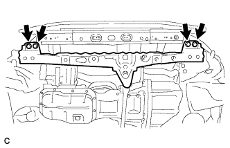
Install the front crossmember with the 4 bolts.
- Torque:
- 96 N*m { 979 kgf*cm, 71 ft.*lbf }
-
Install the front engine mounting insulator to the front crossmember with the 2 bolts.
- Torque:
- 95 N*m { 969 kgf*cm, 70 ft.*lbf }
-
Install the engine mounting insulator LH with the through bolt and nut.
- Torque:
- 56 N*m { 571 kgf*cm, 41 ft.*lbf }
Note
When installing the engine mounting insulator, tighten the nut while holding the bolt.
-
Install the engine mounting insulator RH with the bolt and 2 nuts.
- Torque:
- Nut A
- 95 N*m { 969 kgf*cm, 70 ft.*lbf }
- Nut B
- 52 N*m { 530 kgf*cm, 38 ft.*lbf }
- Bolt
- 95 N*m { 969 kgf*cm, 70 ft.*lbf }
-
Tighten the front engine mounting insulator with the bolt and nut.
- Torque:
- 145 N*m { 1479 kgf*cm, 107 ft.*lbf }
-
-
INSTALL FRONT SUSPENSION CROSSMEMBER SUB-ASSEMBLY
-
Support the front suspension crossmember with a transmission jack.
-
While inserting SST into the reference holes on the front suspension crossmember RH and LH alternately, tighten 2 bolts A, 2 bolts B, C and 2 nuts on the RH and LH sides to the respective specified torque in several steps.
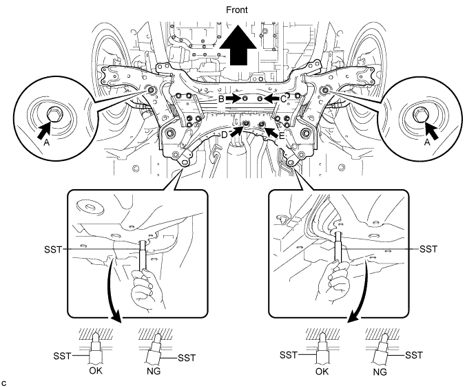
- SST
- 09670-00020
- Torque:
- Bolt A
- 137 N*m { 1397 kgf*cm, 101 ft.*lbf }
- Bolt B, C, Nut D, E
- 95 N*m { 969 kgf*cm, 70 ft.*lbf }
Note
Temporarily tighten bolt B, and then fully tighten the 2 bolts and 2 nuts in the order of C, E, D, and B.
-
Install the 2 wire harness clamp brackets with the 2 bolts.
- Torque:
- 13 N*m { 127 kgf*cm, 9 ft.*lbf }
-
-
INSTALL FRONT SUSPENSION MEMBER REAR BRACE LH
-
Install the front suspension member rear brace LH with the 2 bolts B and bolt A.
- Torque:
- Bolt A
- 137 N*m { 1397 kgf*cm, 101 ft.*lbf }
- Bolt B
- 93 N*m { 948 kgf*cm, 69 ft.*lbf }
-
Install the clip.
-
-
INSTALL FRONT SUSPENSION MEMBER REAR BRACE RH
Tech Tips
Perform the same procedure as for the LH side.
-
INSTALL REAR SIDE RAIL REINFORCEMENT SUB-ASSEMBLY LH
-
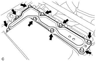
Install the rear side rail reinforcement sub-assembly LH with the 4 bolts.
- Torque:
- 96 N*m { 979 kgf*cm, 71 ft.*lbf }
Note
Temporarily tighten bolts A and B, and then fully tighten the 4 bolts in the order of C, B, D and A.
-
-
INSTALL REAR SIDE RAIL REINFORCEMENT SUB-ASSEMBLY RH
Tech Tips
Perform the same procedure as for the LH side.
-
INSTALL FRONT LOWER ENGINE MOUNTING BRACKET REINFORCEMENT
-
Remove the 2 bolts and front engine mounting bracket lower reinforcement.
-
-
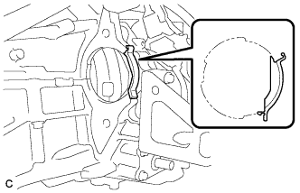
INSTALL FRONT DRIVE SHAFT HOLE SNAP RING LH
-
Install a new front drive shaft hole snap ring to the front drive inboard joint assembly.
Tech Tips
Face the end gap of the front drive inboard joint hole snap ring downward.
-
-
INSTALL FRONT DRIVE SHAFT HOLE SNAP RING RH
Tech Tips
Perform the same procedure as for the LH side.
-
INSTALL FRONT DRIVE SHAFT ASSEMBLY LH
-
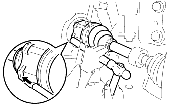
Align the inboard joint splines, and using a brass bar and a hammer, install the front drive shaft assembly.
Note
-
Face the end gap of the front drive shaft hole snap ring downward.
-
Do not damage the transaxle case oil seal.
-
Do not damage the inboard joint boot.
-
Make sure to center the front drive shaft assembly during installation to prevent damage to the front drive shaft hole snap ring.
Tech Tips
Confirm whether the drive shaft is securely driven in by checking the reaction force and sound.
-
-
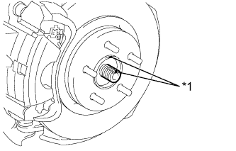
Text in Illustration *1 Matchmark Align the matchmarks and install the front drive shaft assembly to the front axle hub sub-assembly.
-
-
INSTALL FRONT DRIVE SHAFT ASSEMBLY RH
Tech Tips
Perform the same procedure as for the LH side.
-
INSTALL FRONT NO. 1 LOWER SUSPENSION ARM SUB-ASSEMBLY LH
-
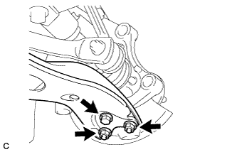
Install the front No. 1 lower suspension arm sub-assembly to the front lower ball joint with the bolt and 2 nuts.
- Torque:
- 89 N*m { 908 kgf*cm, 66 ft.*lbf }
-
-
INSTALL FRONT NO. 1 LOWER SUSPENSION ARM SUB-ASSEMBLY RH
Tech Tips
Perform the same procedure as for the LH side.
-
INSTALL FRONT STABILIZER LINK ASSEMBLY LH
-
Install the front stabilizer link assembly to the front shock absorber with coil spring with the nut.
- Torque:
- 74 N*m { 755 kgf*cm, 55 ft.*lbf }
Tech Tips
If the ball joint turns together with the nut, use a hexagon wrench (6 mm) to hold the stud bolt.
-
-
INSTALL FRONT STABILIZER LINK ASSEMBLY RH
Tech Tips
Perform the same procedure as for the LH side.
-
CONNECT TIE ROD END SUB-ASSEMBLY LH
-
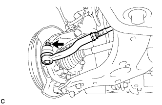
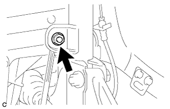
Connect the tie rod end sub-assembly LH to the steering knuckle with the nut.
- Torque:
- 49 N*m { 500 kgf*cm, 36 ft.*lbf }
Note
Further tighten the nut up to 60° if the holes for the clip are not aligned.
-
Install a new clip.
-
-
CONNECT TIE ROD END SUB-ASSEMBLY RH
Tech Tips
Perform the same procedure as for the LH side.
-
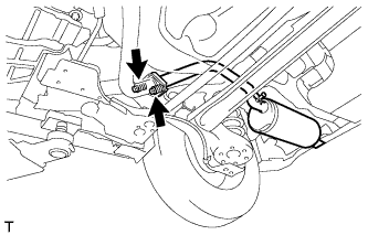
INSTALL FRONT SPEED SENSOR LH
-
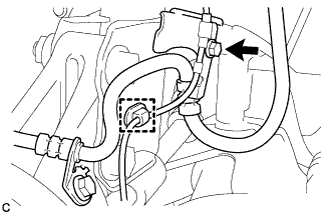
Install the front speed sensor and front flexible hose to the front shock absorber with the bolt and clamp.
- Torque:
- 19 N*m { 192 kgf*cm, 14 ft.*lbf }
Note
Do not twist the front speed sensor when installing it.
Tech Tips
Install the front flexible hose first and then the speed sensor harness bracket.
-
-
INSTALL FRONT SPEED SENSOR RH
Tech Tips
Perform the same procedure as for the LH side.
-
INSTALL FRONT AXLE SHAFT NUT LH
-
Clean the threaded parts on the drive shaft and a new axle shaft nut using a non-residue solvent.
Tech Tips
-
Be sure to perform this work even when using a new drive shaft.
-
Keep the threaded parts free of oil and foreign matter.
-
-
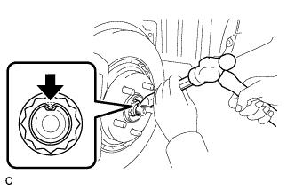
Using a socket wrench (30 mm), install the axle shaft nut.
- Torque:
- 216 N*m { 2203 kgf*cm, 159 ft.*lbf }
-
Using a chisel and hammer, stake the front axle shaft nut.
-
-
INSTALL FRONT AXLE SHAFT NUT RH
Tech Tips
Perform the same procedure as for the LH side.
-
INSTALL FRONT EXHAUST PIPE ASSEMBLY (w/ Exhaust Heat Recirculation System)
Note
When installing the water hose, ensure that the exhaust heat recirculation system is filled with coolant. Otherwise, the engine water pump may be damaged.
-
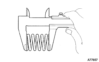
Using a vernier caliper, measure the free length of the compression springs.
Minimum 41.5 mm (1.64 in.) Tech Tips
If the free length is less than minimum, replace the compression spring.
-
Fully insert a new gasket to the exhaust manifold.
-
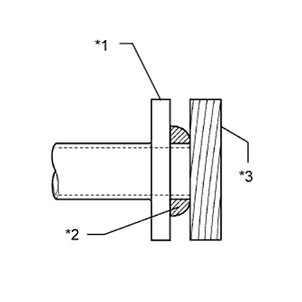
Text in Illustration *1 Exhaust Manifold *2 Gasket *3 Wooden Block Using a plastic hammer and wooden block, tap in the new gasket until its surface is flush with the exhaust manifold.
Note
-
Be careful with the installation direction of the gasket.
-
Do not reuse the gasket.
-
Do not damage the gasket.
-
Do not push in the gasket by using the exhaust pipe when connecting it.
-
-
Connect the front exhaust pipe assembly to the 3 exhaust pipe supports.
-
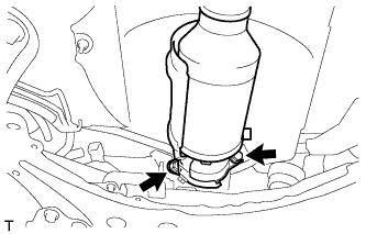
Install the front exhaust pipe assembly with the 2 bolts and 2 compression springs.
- Torque:
- 43 N*m { 440 kgf*cm, 32 ft.*lbf }
-
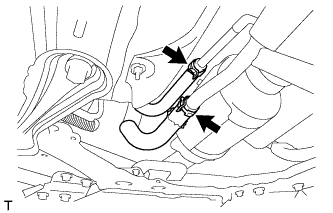
Connect the 2 heater water hoses.
-
-
INSTALL FRONT EXHAUST PIPE ASSEMBLY (w/o Exhaust Heat Recirculation System)
-
Using a vernier caliper, measure the free length of the compression springs.
Minimum 41.5 mm (1.64 in.) Tech Tips
If the free length is less than minimum, replace the compression spring.
-
Fully insert a new gasket to the exhaust manifold.
-
Text in Illustration *1 Exhaust Manifold *2 Gasket *3 Wooden Block Using a plastic hammer and wooden block, tap in the new gasket until its surface is flush with the exhaust manifold.
Note
-
Be careful with the installation direction of the gasket.
-
Do not reuse the gasket.
-
Do not damage the gasket.
-
Do not push in the gasket by using the exhaust pipe when connecting it.
-
-
Connect the front exhaust pipe assembly to the 3 exhaust pipe supports.
-
Install the front exhaust pipe assembly with the 2 bolts and 2 compression springs.
- Torque:
- 43 N*m { 440 kgf*cm, 32 ft.*lbf }
-
-
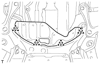
INSTALL FRONT CENTER FLOOR BRACE
-
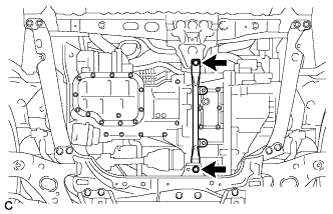
Install the front center floor brace with the 4 bolts.
- Torque:
- 51 N*m { 520 kgf*cm, 38 ft.*lbf }
-
-
INSTALL FRONT NO. 3 ENGINE UNDER COVER
-
Install the front No. 3 engine under cover with the 4 clips.
-
-
INSTALL TAIL EXHAUST PIPE ASSEMBLY
-
Using a vernier caliper, measure the free length of the compression springs.
Minimum 38.5 mm (1.52 in.) Tech Tips
If the free length is less than minimum, replace the compression spring.
-
Fully insert a new gasket to the front exhaust pipe assembly.
-
Text in Illustration *1 Front Exhaust Pipe Assembly *2 Gasket *3 Wooden Block Using a plastic hammer and wooden block, tap in the new gasket until its surface is flush with the front exhaust pipe assembly.
Note
-
Be careful with the installation direction of the gasket.
-
Do not reuse the gasket.
-
Do not damage the gasket.
-
Do not push in the gasket by using the exhaust pipe when connecting it.
-
-
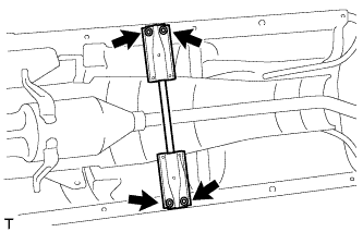
Connect the tail exhaust pipe assembly to the 2 exhaust pipe supports.
-
Install the tail exhaust pipe assembly with the 2 bolts and 2 compression springs.
- Torque:
- 43 N*m { 440 kgf*cm, 32 ft.*lbf }
-
-
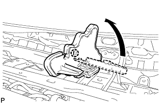
CONNECT NO. 1 STEERING COLUMN HOLE COVER SUB-ASSEMBLY
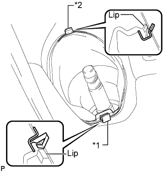
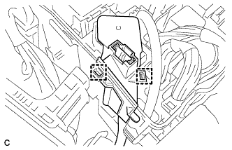
Text in Illustration *1 Clip A *2 Clip B
-
Place clip A as shown in the illustration and engage clip B to the body to connect the No. 1 steering column hole cover sub-assembly.
Note
Make sure that the lips of the No. 1 steering column hole cover sub-assembly are not damaged.
-
-
CONNECT NO. 2 STEERING INTERMEDIATE SHAFT ASSEMBLY
-
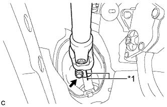
Text in Illustration *1 Matchmark Align the matchmarks on the No. 2 steering intermediate shaft assembly and steering intermediate shaft to connect the No. 2 steering intermediate shaft assembly to the steering intermediate shaft.
-
Install the bolt.
- Torque:
- 35 N*m { 357 kgf*cm, 26 ft.*lbf }
-
-
INSTALL COLUMN HOLE COVER SILENCER SHEET
-
Install the column hole cover silencer sheet with the 2 clips.
-
Install the floor carpet.
-
-
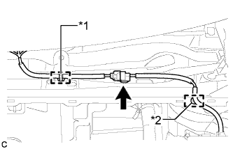
INSTALL WIRE HARNESS
-
Connect the wire harness with the 2 clamps.
-
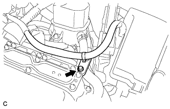
Install the wire harness with the bolt.
- Torque:
- 8.4 N*m { 85 kgf*cm, 74 in.*lbf }
-
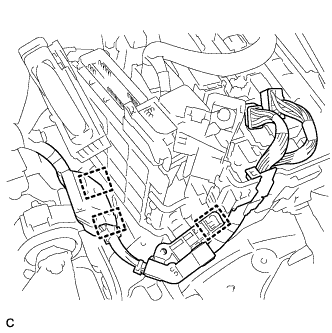
Connect the wire harness with the 3 clamps.
-
Connect the wire harness to the engine room junction block.
-
Connect the 2 connectors and 2 clamps to the engine room junction block.
-
Connect the connector to the ECM with the 2 clamps and lock lever.
-
Connect the 2 clamps.
-
-
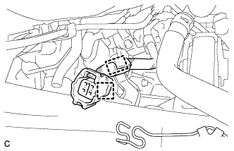
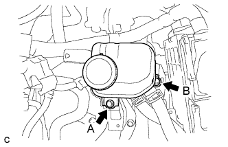
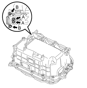
INSTALL ELECTRIC INVERTER COMPRESSOR
-
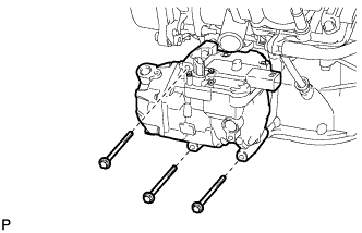
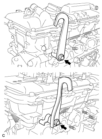
Temporarily install the electric inverter compressor with the 3 bolts.
-
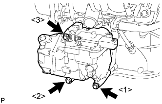
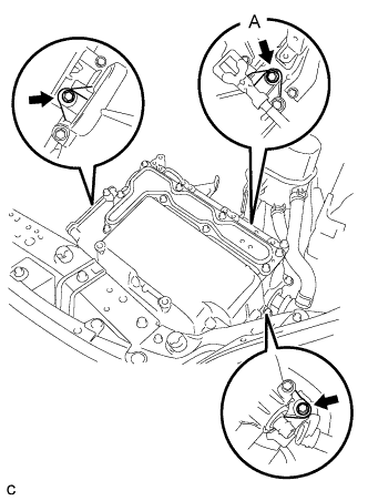
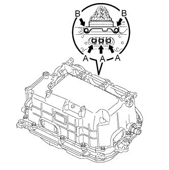
Install the electric inverter compressor with the 3 bolts.
- Torque:
- 25 N*m { 250 kgf*cm, 18 ft.*lbf }
Note
Tighten the bolts in the order shown in the illustration to install the electric inverter compressor.
-
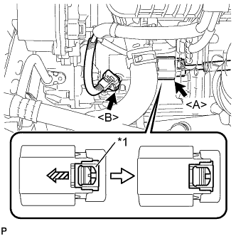
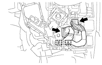
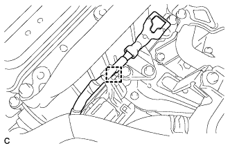
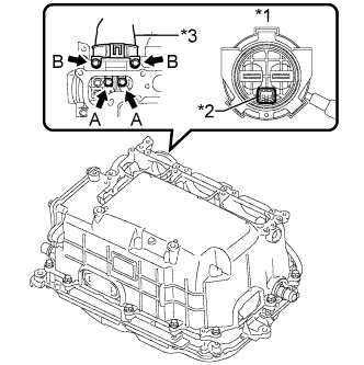
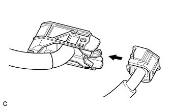
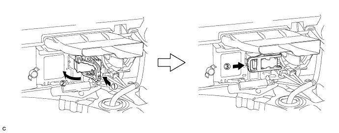
Text in Illustration *1 Green-colored Lock Connect the connector <B>.
-
Connect the connector <A> and slide the green-colored lock in the direction indicated by the arrow in the illustration to lock it securely.
CAUTION:
Make sure to wear insulating gloves.
Note
Make sure that the connector is connected securely.
-
-
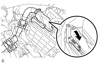
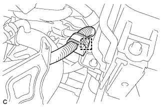
CONNECT FUEL TUBE SUB-ASSEMBLY
-
Connect the fuel tube connector and fuel pipe.
CAUTION:
Align the fuel tube connector with the pipe, then push the fuel tube connector in until the retainer makes a "click" sound. If the connection is tight, apply a small amount of engine oil to the tip of the pipe. After connecting, pull the pipe and connector to make sure that they are securely connected.
-
Engage the claw and install the No. 1 fuel pipe clamp.
-
-
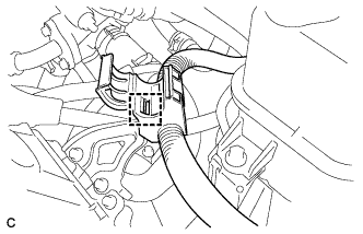
CONNECT NO. 1 FUEL VAPOR FEED HOSE
-
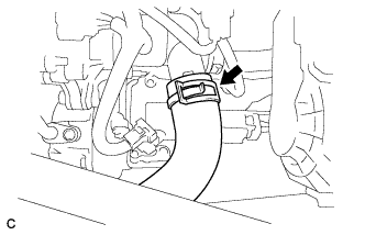
Connect the No. 1 fuel vapor feed hose with the clamp.
-
-
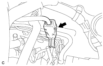
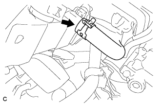
CONNECT HEATER HOSE
-
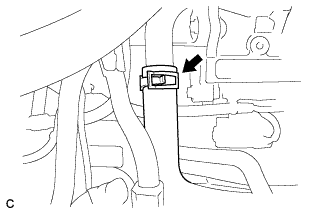
Connect the heater hose with the clamp.
-
-
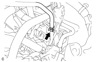
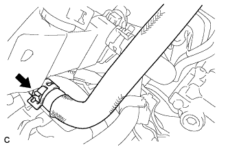
CONNECT INLET HEATER WATER HOSE
-
Connect the inlet heater water hose with the clamp.
-
-
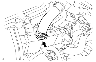
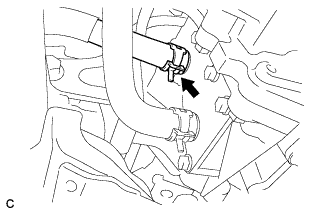
CONNECT OUTLET HEATER WATER HOSE
-
Connect the outlet heater water hose with the clamp.
-
-
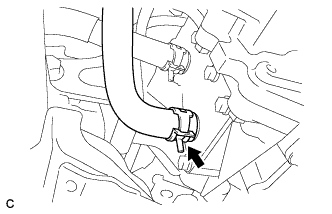
CONNECT NO. 5 INVERTER COOLING HOSE
-
Connect the No. 5 inverter cooling hose with the clamp.
-
-
CONNECT NO. 3 INVERTER COOLING HOSE
-
Connect the No. 3 inverter cooling hose with the clamp.
-
-
CONNECT NO. 4 WATER BY-PASS HOSE
-
Connect the No. 4 water by-pass hose with the clamp.
-
-
CONNECT NO. 2 RADIATOR HOSE
-
Connect the No. 2 radiator hose with the clamp.
-
-
CONNECT NO. 1 RADIATOR HOSE
-
Connect the No. 1 radiator hose with the clamp.
-
-
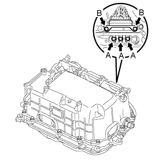
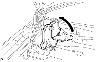
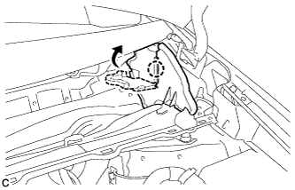
INSTALL INVERTER TRAY BRACKET
-
Position the inverter tray bracket as shown in the illustration.
-
Temporarily install bolt B to the inverter tray bracket.
-
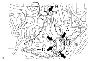
Tighten the 5 bolts to the inverter tray bracket in the order the bolt A, bolt C, bolt D, bolt E and bolt B.
- Torque:
- 18 N*m { 184 kgf*cm, 13 ft.*lbf }
-
Connect the 2 clamps to the inverter tray bracket.
-
-
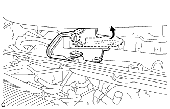
INSTALL INVERTER RESERVE TANK ASSEMBLY
-
Temporarily install bolt A to the inverter reserve tank assembly.
-
Tighten the 2 bolts to the inverter reserve tank assembly in the order the bolt B and bolt A.
- Torque:
- 10 N*m { 102 kgf*cm, 7 ft.*lbf }
-
-
INSTALL INVERTER WITH CONVERTER ASSEMBLY
CAUTION:
Wear insulating gloves.
-
Temporarily install the inverter with converter assembly with the 3 bolts.
Note
-
Since the inverter with converter assembly is very heavy, 2 people are needed to install the inverter with converter assembly. When installing the inverter with converter assembly, do not damage the parts around it.
-
To prevent damage, do not hold the inverter with converter assembly by the connectors.
-
To prevent damage due to static electricity, do not touch the terminals of the disconnected connectors.
-
-
Tighten the bolt A.
- Torque:
- 12 N*m { 122 kgf*cm, 8 ft.*lbf }
-
Tighten the 2 bolts.
- Torque:
- 12 N*m { 122 kgf*cm, 8 ft.*lbf }
-
-
CONNECT WATER HOSE
-
Connect the water hose to the inverter with converter assembly and lock the hose with the retainer.
Note
-
Insert the retainer until a click sound is heard.
-
Pull on the hose to confirm that the hose is securely connected.
-
If there is foreign matter on the union or the O-ring, clean it with water and finger scouring.
-
-
-
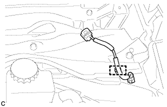
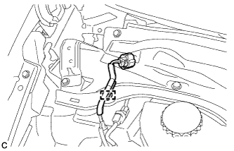
CONNECT NO. 2 ENGINE ROOM WIRE
-
Disconnect the No. 2 engine room wire from the protector.
-
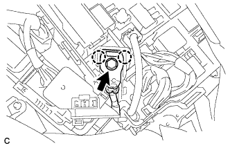
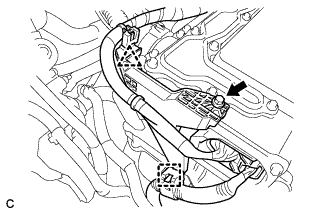
Connect the No. 2 engine room wire with the bolt and 2 claws.
- Torque:
- 8.3 N*m { 85 kgf*cm, 73 in.*lbf }
Note
Pass the No. 2 engine room wire under the two cooling hoses that pass beside the inverter.
-
Install the No. 1 relay block cover and 2 clamps.
-
Install the relay block cover.
-
-
REMOVE INVERTER TERMINAL COVER
CAUTION:
Wear insulating gloves.
-
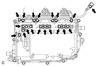
Remove the 9 bolts and inverter terminal cover.
Note
Make sure to pull the inverter terminal cover straight up, as a connector is connected to the bottom of the cover.
-
-
CONNECT NO. 2 ENGINE WIRE
CAUTION:
Wear insulating gloves.
Note
Do not allow any foreign objects or water to enter the inverter with converter assembly.
-
Connect the No. 2 engine wire (high voltage cables of the air conditioning) with the 4 bolts to the inverter with converter assembly.
- Torque:
- Bolt A
- 8.0 N*m { 82 kgf*cm, 71 in.*lbf }
- Bolt B
- 9.2 N*m { 94 kgf*cm, 81 in.*lbf }
Note
Be sure to use a torque wrench to tighten the bolts.
-
Connect the harness clamp.
-
-
CONNECT HIGH VOLTAGE CABLE OF FRONT TRANSAXLE
CAUTION:
Wear insulating gloves.
Note
Do not allow any foreign objects or water to enter the inverter with converter assembly.
-
Connect the high voltage cable of the motor (MG2) with 5 bolts to the inverter with converter assembly.
- Torque:
- Bolt A
- 8.0 N*m { 82 kgf*cm, 71 in.*lbf }
- Bolt B
- 9.2 N*m { 94 kgf*cm, 81 in.*lbf }
Note
Be sure to use a torque wrench to tighten the bolts.
-
Connect the harness clamp.
-
Connect the high voltage cable of the generator (MG1) with the 5 bolts to the inverter with converter assembly.
- Torque:
- Bolt A
- 8.0 N*m { 82 kgf*cm, 71 in.*lbf }
- Bolt B
- 9.2 N*m { 94 kgf*cm, 81 in.*lbf }
Note
Be sure to use a torque wrench to tighten the bolts.
-
Text in Illustration *1 Align Mark Install the cable and cover.
Note
Close the cover so that the matchmarks are not visible.
-
-
CONNECT FRAME WIRE
CAUTION:
Wear insulating gloves.
Note
-
Make sure that the interlock is fully engaged.
-
Do not allow any foreign objects or water to enter the inverter with converter assembly.
-
Text in Illustration *1 Front view of frame wire connector *2 Interlock *3 High voltage cables of the hybrid battery Connect the frame wire (high voltage cables of the hybrid battery) with the 4 bolts to the inverter with converter assembly.
- Torque:
- Bolt A
- 8.0 N*m { 82 kgf*cm, 71 in.*lbf }
- Bolt B
- 9.2 N*m { 94 kgf*cm, 81 in.*lbf }
Note
-
Be sure to use a torque wrench to tighten the bolts.
-
Make sure that the interlock is fully engaged.
-
Connect the harness clamp.
-
-
CHECK HIGH VOLTAGE CABLE CONNECTION
CAUTION:
Wear insulating gloves.
Note
Do not allow any foreign objects or water to enter the inverter with converter assembly.
-
Check that each connector and terminal is firmly installed.
Note
Make sure that the bolts are fully tightened.
-
-
INSTALL INVERTER TERMINAL COVER
CAUTION:
Wear insulating gloves.
Note
-
Make sure that the interlock is fully engaged.
-
Do not allow any foreign objects or water to enter the inverter with converter assembly.
-
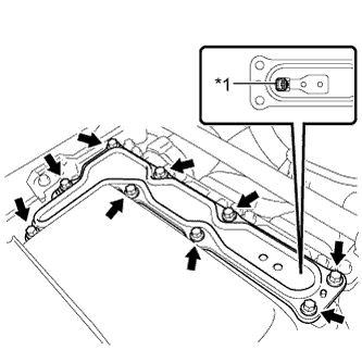
Text in Illustration *1 Interlock Install the inverter terminal cover with the 9 bolts to the inverter with converter assembly.
- Torque:
- 11 N*m { 112 kgf*cm, 8 ft.*lbf }
-
-
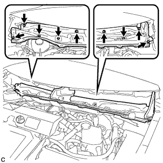
CONNECT ENGINE ROOM MAIN WIRE
Note
-
Make sure that the connectors are fully engaged.
-
Do not allow any foreign objects or water to enter the inverter with converter assembly.
-
Install the bolt, clamp and clip, and connect the engine room main ware.
- Torque:
- 12 N*m { 122 kgf*cm, 9 ft.*lbf }
-
Install the bolt.
- Torque:
- 12 N*m { 122 kgf*cm, 9 ft.*lbf }
-
Connect the engine wire to the engine room main wire.
-
Connect the connector to the inverter with converter assembly and lock the connector with the lock lever.
-
-
INSTALL NO. 1 INVERTER BRACKET
-
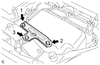
Temporarily install the No. 1 inverter bracket with the 3 bolts.
-
Tighten the 3 bolts in the order shown in the illustration.
- Torque:
- 14 N*m { 140 kgf*cm, 10 ft.*lbf }
-
-
INSTALL AIR CLEANER HOSE ASSEMBLY
-
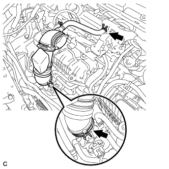
Install the air cleaner hose assembly and lock the hose clamp.
-
Connect the ventilation hose.
-
-
INSTALL AIR CLEANER CASE
-
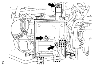
Install the air cleaner case with the 3 bolts.
- Torque:
- 7.0 N*m { 71 kgf*cm, 62 in.*lbf }
-
Connect the No. 4 water by-pass hose to the air cleaner case with the 3 clamps.
-
Install the air cleaner filter element.
-
-
INSTALL INLET AIR CLEANER ASSEMBLY
-
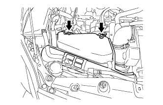
Install the inlet air cleaner assembly with the 2 bolts.
- Torque:
- 7.0 N*m { 71 kgf*cm, 62 in.*lbf }
-
-
INSTALL AIR CLEANER CAP SUB-ASSEMBLY
-
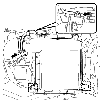
Install the air cleaner cap sub-assembly with the 2 clamps and hose band.
-
Connect the air flow meter connector.
-
-
INSTALL SERVICE PLUG GRIP
CAUTION:
Wear insulating gloves.
Note
Before connecting the service plug, check that no parts and tools remain and that the high voltage terminals and connectors are connected securely.
-
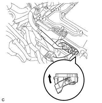
Wear insulated gloves and install the service plug grip in the order shown in the illustration.
-
Rotate the handle of the service plug grip 90° toward the battery and slide it in the direction shown by the arrow until a click sound is heard.
-
-
CONNECT CABLE TO NEGATIVE BATTERY TERMINAL
Note
When disconnecting the cable, some systems need to be initialized after the cable is reconnected Click here.
-
INSTALL REAR NO. 3 FLOOR BOARD
-

Engage the 2 guides to install the rear No. 3 floor board.
-
-
INSTALL REAR DECK FLOOR BOX
-
Install the rear deck floor box.
-
-
INSTALL REAR NO. 2 FLOOR BOARD
-

Engage the 3 guides <A>.
-
Engage the 2 guides <B> and install the rear No. 2 floor board as shown in the illustration.
-
-
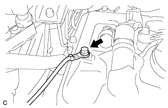
ADD HYBRID TRANSAXLE FLUID
-
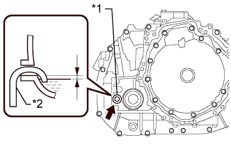
Text in Illustration *1 Filler Plug *2 Filler Nozzle Add transaxle fluid until the fluid level is between 0 to 10 mm (0 to 0.394 in.) from the bottom lip of the filler plug opening.
Note
-
Stop the vehicle on a level surface.
-
Use Toyota Genuine ATF WS.
-
Be sure to fully insert the filler nozzle into the filler plug opening.
-
Be sure to add fluid slowly. If fluid is added quickly, the fluid may hit internal parts and bounce back, resulting in fluid coming out of the filler plug opening.
-
Be sure to directly check that the transaxle fluid level is within the specified range.
-
Insufficient or excessive amounts of transaxle fluid may damage the hybrid transaxle.
Reference 3.4 liters (3.6 US qts, 3.0 lmp.qts) -
-
After adding fluid, leave it for 30 seconds so that the fluid surface can become still again, and then check that the fluid level is between 0 to 10 mm (0 to 0.394 in.) from the bottom lip of the filler plug opening. (If the fluid is insufficient, return to the Add Hybrid Transaxle Fluid procedure.)
-
Using a 10 mm hexagon socket wrench, install the filler plug with a new gasket.
- Torque:
- 50 N*m { 510 kgf*cm, 37 ft.*lbf }
-
-
INSPECT HYBRID TRANSAXLE FLUID
-
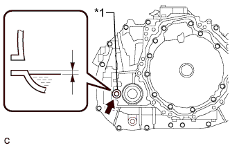
Text in Illustration *1 Filler Plug Using a 10 mm hexagon socket wrench, remove the filler plug and gasket.
-
Check that the fluid level is between 0 to 10 mm (0 to 0.394 in.) from the bottom lip of the filler plug opening. (If the fluid is insufficient, return to the Add Hybrid Transaxle Fluid procedure.)
Note
-
Stop the vehicle on a level surface.
-
Be sure to directly check that the transaxle fluid level is within the specified range.
-
Insufficient or excessive amounts of transaxle fluid may damage the hybrid transaxle.
-
Recheck the transaxle fluid level after driving following fluid replacement.
-
-
Check for leaks if the quantity of transaxle fluid is low.
-
Using a 10 mm hexagon socket wrench, install the filler plug with a new gasket.
- Torque:
- 50 N*m { 510 kgf*cm, 37 ft.*lbf }
-
-
ADD COOLANT (for Engine)
-
Tighten the radiator drain cock plug.
-
Remove the reservoir tank cap.
-
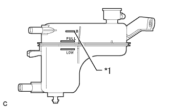
Text in Illustration *1 B Line Add coolant to B line of the reservoir tank.
Standard Capacity Item Capacity Engine coolant w/ Exhaust Heat Recirculation System:
7.2 liters (7.6 US qts, 6.3 lmp. qts)
w/o Exhaust Heat Recirculation System:
6.5 liters (6.8 US qts, 5.7 lmp. qts)
Tech Tips
TOYOTA vehicles are filled with TOYOTA SLLC at the factory. In order to avoid damage to the engine cooling system and other technical problems, only use TOYOTA SLLC or similar high quality ethylene glycol based non-silicate, non-amine, non-nitrite, non-borate coolant with long-life hybrid organic acid technology (coolant with long-life hybrid organic acid technology is a combination of low phosphates and organic acids).
Note
Never use water as a substitute for engine coolant.
-
Squeeze the inlet and outlet radiator hoses several times by hand, and then check the level of the coolant.
If the coolant level is low, add coolant.
-
Install the reservoir tank cap.
-
Put the engine in inspection mode Click here.
-
Bleed air from the cooling system.
Note
-
Before starting the engine, turn the A/C switch off.
-
Adjust the heater control to the maximum hot setting.
-
Adjust the blower speed to low setting.
-
Warm up the engine until the thermostat opens. While the thermostat is open, allow the coolant to circulate for several minutes.
Tech Tips
The thermostat opening timing can be confirmed by squeezing the inlet radiator hose by hand, and sensing vibrations when the engine coolant starts to flow inside the hose.
CAUTION:
When squeezing the radiator hose:
-
Wear protective gloves.
-
Be careful as the radiator hoses are hot.
-
Keep your hands away from the radiator fan.
-
-
Squeeze the inlet and outlet radiator hoses several times by hand to bleed air from the system.
CAUTION:
When squeezing the radiator hose:
-
Wear protective gloves.
-
Be careful as the radiator hoses are hot.
-
Keep your hands away from the radiator fan.
-
-
-
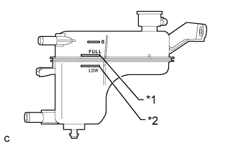
Text in Illustration *1 Full Line *2 Low Line After the engine has cooled down, check that the coolant level is between full and low.
If the coolant level is low, add coolant to the full line on the reservoir tank.
-
-
ADD COOLANT (for Inverter)
Note
-
Do not reuse the drained coolant because it may contain foreign objects.
-
If the vehicle is driven with air in the inverter cooling system, damage may occur and the following DTCs may be set.
DTC Code Detection Item P0A01-726 Motor Electronics Coolant Temperature Sensor Circuit Range / Performance P0A04-725 Motor Electronics Coolant Temperature Sensor Circuit Intermittent P0A08-264 DC / DC Converter Status Circuit P0A78-284 Drive Motor "A" Inverter Performance P0A78-286 Drive Motor "A" Inverter Performance P0A7A-322 Generator Inverter Performance P0A7A-324 Generator Inverter Performance P0A93-346 Inverter Cooling System Performance P0A94-553 DC / DC Converter Performance P0A94-557 DC / DC Converter Performance P0AEE-277 Motor Inverter Temperature Sensor "A" Circuit Range / Performance P0AF1-276 Drive Motor Inverter Temperature Sensor "A" Circuit Intermittent / Erratic P0BCD-315 Generator Inverter Temperature Sensor Circuit Range / Performance P0BD0-314 Generator Inverter Temperature Sensor Circuit Intermittent / Erratic P0C39-626 DC / DC Converter Temperature Sensor "A" Range / Performance P0C3C-625 DC / DC Converter Temperature Sensor "A" Intermittent / Erratic P0C3E-628 DC / DC Converter Temperature Sensor "B" Range / Performance P0C41-627 DC / DC Converter Temperature Sensor "B" Intermittent / Erratic P0C73-776 Motor Electronics Coolant Pump "A" Control Performance
-
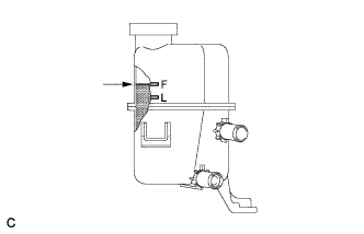
Slowly pour coolant into the reserve tank until it reaches the F line.
Coolant quantity 2.1 liters (2.2 US qts, 1.8 Imp. qts.) -
When using the intelligent tester:
-
Connect the intelligent tester to the DLC3.
-
Turn the power switch on (IG).
-
On the intelligent tester, enter the following menus: Powertrain / Hybrid Control / Active Test / Activate the Water Pump.
-
Keep the coolant at the F line in the reserve tank to compensate for the drop in coolant level when the air bleeds.
Standard Air bleeding from the inverter cooling system is completed when the noise made by the water pump becomes smaller and the circulation of coolant in the reserve tank improves. Tech Tips
Loud noise made by the water pump and poor circulation of coolant in the reserve tank indicates that there is air in the cooling system.
-
-
When not using the intelligent tester:
-
Turn the power switch on (READY). [*1]
-
Turn the power switch off and add coolant to the F line because the coolant level drops as the air bleeds. [*2]
Note
-
Be sure to turn the power switch off before adding SLLC.
-
Do not work on the components in the engine compartment while the vehicle is in the READY-on state because the engine is in intermittent operation.
-
-
Repeat steps [*1] and [*2] until air bleeding from the cooling system is completed.
Standard Air bleeding from the inverter cooling system is completed when the noise made by the water pump becomes smaller and the circulation of coolant in the reserve tank improves. Tech Tips
Loud noise made by the water pump and poor circulation of coolant in the reserve tank indicates that there is air in the cooling system.
-
-
After the air is completely bled from the cooling system, tighten the reserve tank cap.
-
Add coolant to the F line of the reserve tank.
-
-
ADD ENGINE OIL
-
Add new engine oil and install the oil filler cap.
Standard Oil Grade Oil Grade Oil Viscosity (SAE) API grade SL "energy-conserving", SM "energy-conserving", SN "resource-conserving" or ILSAC multigrade engine oil
-
0W-20
-
5W-20
-
5W-30
-
10W-30
API grade SL, SM or SN multigrade engine oil
-
15W-40
-
20W-50
Standard Capacity Item Standard Condition Drain and refill with oil filter change 4.2 liters (4.4 US qts, 3.7 lmp. qts) Drain and refill without oil filter change 3.9 liters (4.1 US qts, 3.4 lmp. qts) Dry fill 4.7 liters (5.0 US qts, 4.1 lmp. qts) -
-
-
INSPECT ENGINE OIL LEVEL
-
Put the engine in inspection mode Click here.
-
Warm up and stop the engine, then wait for 5 minutes. The oil level should be between the low level and full level marks on the engine oil level dipstick. If the engine oil level is low, check for leakage and add oil up to the full level mark.
Note
Do not fill with engine oil to above the full level mark.
-
-
INSPECT FOR FUEL LEAK
-
Check fuel pump operation.
-
Connect the intelligent tester to the DLC3.
-
Turn the power switch on (IG).
Note
Do not start the engine.
-
Turn the intelligent tester on.
-
Enter the following menus: Powertrain / Engine and ECT / Active Test / Control the Fuel Pump /Speed.
-
Check for pressure in the fuel inlet tube from the fuel line. Check that sounds of fuel flowing from the fuel tank can be heard. If no sounds can be heard, check the integration relay, fuel pump, ECM and wiring connectors.
-
-
Inspect for fuel leaks.
-
Check that there is no fuel leakage after performing maintenance anywhere on the fuel system. If there is a fuel leak, repair or replace parts as necessary.
-
-
Turn the power switch off.
-
Disconnect the intelligent tester from the DLC3.
-
-
INSPECT FOR COOLANT LEAK (for Engine)
CAUTION:
Do not remove the reservoir tank cap while the engine and radiator are still hot. Pressurized, hot engine coolant and steam may be released and cause serious burns.
Note
Before performing each inspection, turn the A/C switch off.
-
Remove the reservoir tank cap.
-
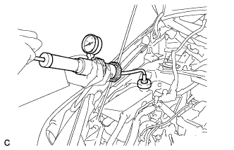
Fill the radiator and reservoir with coolant, and then attach a radiator cap tester.
-
Put the engine in inspection mode Click here.
-
Warm up the engine.
-
Using the reservoir cap tester, increase the pressure inside the radiator to 108 kPa (1.1 kgf/cm2, 16 psi), and check that the pressure does not drop. If the pressure drops, check the hoses, radiator, front exhaust pipe assembly and the heater hose around and engine water pump assembly for leaks. If no external leaks are found, check the heater core, cylinder block and cylinder head.
-
Remove the radiator cap tester.
-
Install the reservoir tank cap.
-
-
INSPECT FOR COOLANT LEAK (for Inverter)
-
Remove the reserve tank cap.
CAUTION:
To avoid the danger of being burned, do not remove the reserve tank cap while the coolant for the inverter is still hot.
-
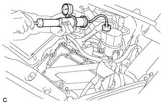
Install the radiator cap tester.
-
Pump the radiator cap tester to 122 kPa (1.2 kgf/ cm2, 17.7 psi), and then check that the pressure does not drop.
Tech Tips
If the pressure drops, check the hoses, radiator, water pump, inverter with converter, and hybrid vehicle transaxle assembly for leaks.
-
Reinstall the reserve tank cap.
-
-
INSPECT FOR OIL LEAK
-
INSPECT FOR EXHAUST GAS LEAK
-
INSTALL NO. 2 ENGINE UNDER COVER
-
INSTALL NO. 1 ENGINE UNDER COVER
-
INSTALL FRONT LOWER BUMPER ABSORBER (w/ Cover)
-
INSTALL FRONT SPOILER COVER (w/ Front Spoiler)
-
INSTALL REAR ENGINE UNDER COVER LH
-
INSTALL REAR ENGINE UNDER COVER RH
-
INSTALL FRONT WHEELS
- Torque:
- 103 N*m { 1050 kgf*cm, 76 ft.*lbf }
-
INSPECT IGNITION TIMING
-
Put the engine in inspection mode Click here.
-
Warm up and stop the engine.
-
When using the intelligent tester:
Check the ignition timing.
-
Connect the intelligent tester to the DLC3.
-
Put the engine in inspection mode Click here.
-
Turn the intelligent tester on.
-
Enter the following menus: Powertrain / Engine and ECT / Data List / IGN Advance.
Standard ignition timing 0 to 16 degrees BTDC Note
-
Check the ignition timing with the cooling fans off.
-
Turn off all electrical systems and the A/ C.
-
When checking the ignition timing, the transaxle should be in neutral or park.
Tech Tips
Refer to the intelligent tester operator's manual for further details.
-
-
Check that the ignition timing advances immediately when the engine speed is increased.
-
Enter the following menus: Powertrain / Engine and ECT / Active Test / Connect the TC and TE1 / ON.
-
Monitor IGN Advance of the Data List.
Standard ignition timing 8 to 12 degrees BTDC Note
When checking the ignition timing, the transaxle should be in neutral or park.
Tech Tips
Refer to the intelligent tester operator's manual for further details.
-
Enter the following menus: Connect the TC and TE1 / OFF.
-
Turn the power switch off.
-
Turn the intelligent tester off.
-
Disconnect the intelligent tester from the DLC3.
-
-
When not using the intelligent tester:
-
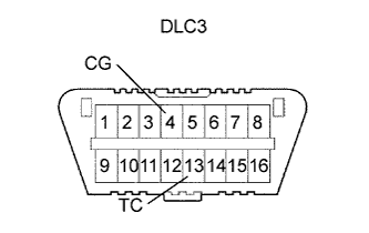
Using SST, connect terminals 13 (TC) and 4 (CG) of the DLC3.
- SST
- 09843-18040
Note
-
Be sure to connect the terminals correctly. Failure to do this can damage the engine.
-
Check the ignition timing with the cooling fans off.
-
Turn off all electrical systems and the A/ C.
-
When checking the ignition timing, the transaxle should be in neutral or park.
-
Remove the No. 2 cylinder head cover Click here.
-
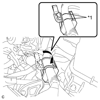
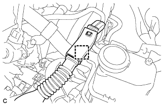
Pull out the wire harness shown in the illustration.
Note
After checking, wrap the wire harness with tape.
-
Connect the clip of the timing light to the wire harness.
Note
Use a timing light that detects the primary signal.
-
Inspect the ignition timing at idle.
Standard ignition timing 8 to 12 degrees BTDC Note
When checking the ignition timing, the transaxle should be in neutral or park.
Tech Tips
After running the engine at 1000 to 1300 rpm for 5 seconds, check that it returns to idle speed.
-
Disconnect terminals 13 (TC) and 4 (CG) of the DLC3.
-
Inspect the ignition timing at idle.
Standard ignition timing 0 to 16 degrees BTDC -
Confirm that the ignition timing advances when the engine rpm is increased.
-
Remove the timing light.
-
Install the No. 2 cylinder head cover Click here.
-
-
-
INSPECT ENGINE IDLE SPEED
-
Put the engine in inspection mode Click here.
-
Warm up and stop the engine.
-
Connect the intelligent tester to the DLC3.
-
Put the engine in inspection mode Click here.
-
Turn the intelligent tester on.
-
Enter the following menus: Powertrain / Engine and ECT / Data List / Engine Speed.
Tech Tips
Refer to the intelligent tester operator's manual for further details.)
-
Inspect the engine idle speed.
Standard idle speed 950 to 1050 rpm Note
-
Turn all electrical systems and the A/C off.
-
Inspect the idle speed with the cooling fans off.
-
When checking the idle speed, the transaxle should be in neutral or park.
-
-
Turn the power switch off.
-
Turn the intelligent tester off.
-
Disconnect the intelligent tester from the DLC3.
-
-
INSPECT CO/HC
Tech Tips
This check determines whether or not the idle CO / HC complies with regulations.
-
Put the engine in inspection mode Click here.
-
Warm up the engine.
-
Run the engine at 2500 rpm for approximately 180 seconds.
-
Insert a CO/HC meter testing probe at least 40 cm (1.3 ft.) into the tailpipe while idling.
-
Check the CO/HC concentration while idling and when the engine is running at 2500 rpm.
Tech Tips
When doing a 2 mode (with the engine idling/ running at 2500 rpm) test, the measurement procedures are determined by applicable local regulations.
If the CO/HC concentration does not comply with the regulations, troubleshoot in the order given below.
-
Check the DTCs Click here.
-
See the table below for possible causes, then inspect the applicable parts and repair them if necessary.
CO HC Problem Possible Cause Normal High Rough idle
-
Faulty ignition:
-
Incorrect timing
-
Fouled, shorted or improperly gapped plugs
-
Incorrect valve clearance
-
Leaks from intake and exhaust valves
-
Leaks from cylinders
-
Faulty EGR
Low High Rough idle (Fluctuating HC reading)
-
Vacuum leaks:
-
PCV hoses
-
Intake manifold
-
Throttle body
-
Brake booster line
-
Lean mixture causing misfire
-
Faulty EGR
High High Rough idle (Black smoke from exhaust)
-
Restricted air cleaner filter element
-
Plugged PCV valve
-
Faulty EFI systems:
-
Faulty pressure regulator
-
Faulty engine coolant temperature sensor
-
Faulty mass air flow meter
-
Faulty ECM
-
Faulty injectors
-
Throttle body
-
Faulty EGR
-
-
-
-
INSPECT AND ADJUST FRONT WHEEL ALIGNMENT
Tech Tips
-
INSTALL NO. 2 CYLINDER HEAD COVER
-
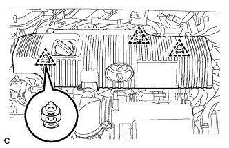
Engage the 3 clips to install the cover.
Note
-
Be sure to engage the clips securely.
-
Do not apply excessive force or hit the cover to engage the clips. This may cause the cover to break.
-
-
-
INSTALL RADIATOR SUPPORT OPENING COVER
-
Engage the 2 claws and install the radiator support opening cover.
-
Install the 3 clips.
-
-
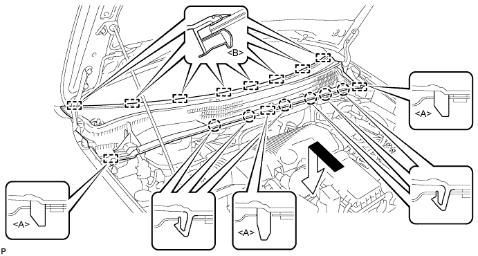
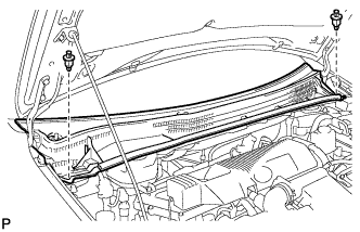
INSTALL OUTER COWL TOP PANEL SUB-ASSEMBLY (for LHD)
-
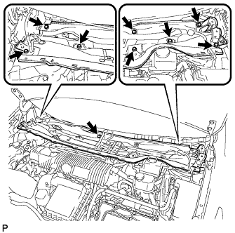
Install the outer cowl top panel sub-assembly with the 9 bolts.
- Torque:
- 12 N*m { 122 kgf*cm, 9 ft.*lbf }
-
Bend the water guard plate RH and engage the claw.
-
Bend the No. 1 heater air duct splash shield seal and engage the claw.
-
Engage the clamp to install the wire harness.
-
-
INSTALL OUTER COWL TOP PANEL SUB-ASSEMBLY (for RHD)
-
Install the outer cowl top panel with the 9 bolts.
- Torque:
- 12 N*m { 122 kgf*cm, 9 ft.*lbf }
-
Bend the water guard plate RH and engage the claw.
-
Bend the No. 1 heater air duct splash shield seal and engage the claw.
-
Engage the clamp*2 of the wire harness.
-
Engage the clamp*1 and connect the connector (w/ Windshield Deicer).
-
Engage the clamp of the wire harness.
-
-
INSTALL COWL BODY MOUNTING REINFORCEMENT LH (for LHD)
-
Install the cowl body mounting reinforcement LH with the 3 bolts.
- Torque:
- 12 N*m { 122 kgf*cm, 9 ft.*lbf }
-
-
INSTALL COWL BODY MOUNTING REINFORCEMENT LH (for RHD)
-
Install the cowl body mounting reinforcement LH with the 3 bolts.
- Torque:
- 12 N*m { 122 kgf*cm, 9 ft.*lbf }
-
-
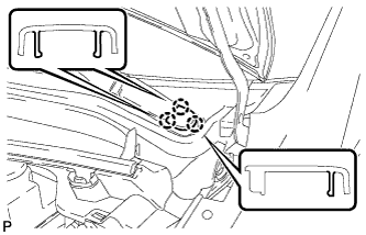
INSTALL WINDSHIELD WIPER MOTOR AND LINK ASSEMBLY
-
Connect the connector.
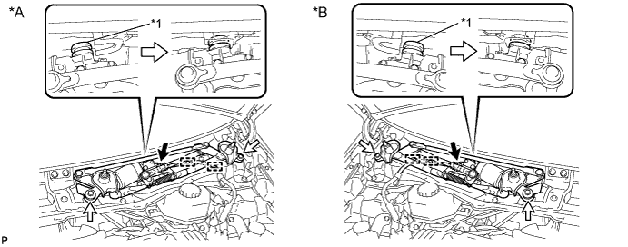
Text in Illustration *A for LHD: *B for RHD: *1 Grommet - - -
Engage the grommet as shown in the illustration.
-
Install the windshield wiper motor and link assembly with the 2 bolts.
- Torque:
- 5.5 N*m { 56 kgf*cm, 49 in.*lbf }
-
Engage the 2 clamps.
Note
Be careful not to damage the windshield when installing the windshield wiper motor and link assembly.
-
-
INSTALL COWL TOP VENTILATOR LOUVER SUB-ASSEMBLY (for LHD)
-
Engage the 8 guides <B>.
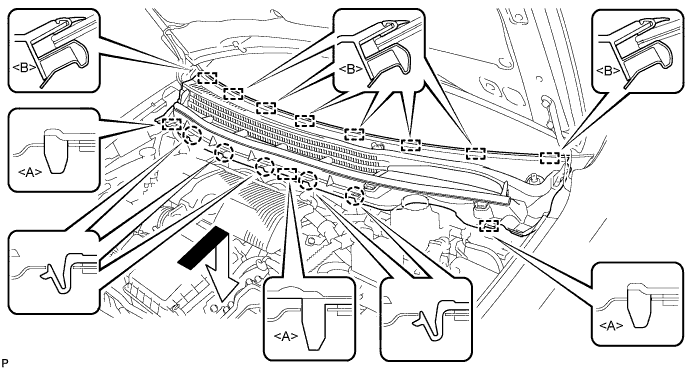
-
Engage the 5 claws and 3 guides <A> to install the cowl top ventilator louver sub-assembly as shown in the illustration.
-
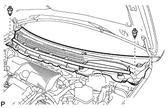
Install the 2 clips.
-
-
INSTALL COWL TOP VENTILATOR LOUVER SUB-ASSEMBLY (for RHD)
-
Engage the 8 guides <B>.
-
Engage the 6 claws and 3 guides <A> to install the cowl top ventilator louver sub-assembly as shown in the illustration.
-
Install the 2 clips.
-
-
INSTALL COWL SIDE VENTILATOR SUB-ASSEMBLY LH
-
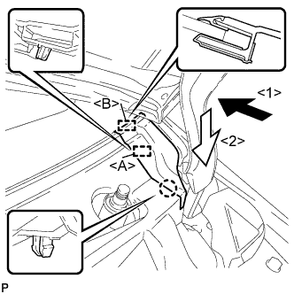
Engage the guide <B> as shown in the illustration.
-
Engage the claw and guide <A> to install the cowl side ventilator sub-assembly LH as shown in the illustration.
-
-
INSTALL COWL SIDE VENTILATOR SUB-ASSEMBLY RH
Tech Tips
Use the same procedure for the RH side and LH side.
-
INSTALL FRONT WIPER ARM AND BLADE ASSEMBLY RH
-
Operate the wiper and stop the windshield wiper motor at the automatic stop position.
-
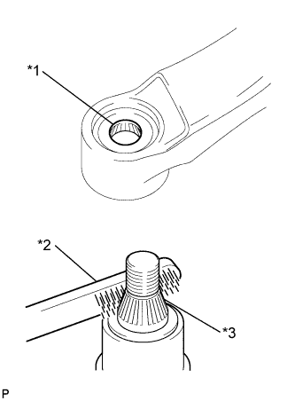
Text in Illustration *1 Wiper Arm Serration *2 Wire Brush *3 Wiper Pivot Serration When reusing the front wiper arm and blade assembly RH:
-
Clean the wiper arm serrations.
-
-
When reusing the windshield wiper link assembly:
-
Clean the wiper pivot serrations with a wire brush.
-
-
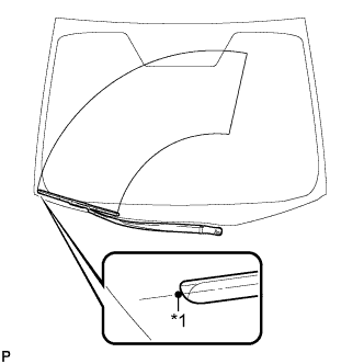
Text in Illustration *1 Ceramic Dot Install the front wiper arm and blade assembly RH with the nut to the position shown in the illustration.
- Torque:
- 23 N*m { 235 kgf*cm, 17 ft.*lbf }
Tech Tips
Hold the wiper arm by hand while tightening the nut.
-
-
INSTALL FRONT WIPER ARM AND BLADE ASSEMBLY LH
-

Text in Illustration *1 Wiper Arm Serration *2 Wire Brush *3 Wiper Pivot Serration When reusing the front wiper arm and blade assembly LH:
-
Clean the wiper arm serrations.
-
-
When reusing the windshield wiper link assembly:
-
Clean the wiper pivot serrations with a wire brush.
-
-
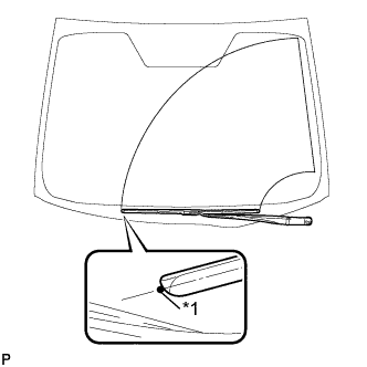
Text in Illustration *1 Ceramic Dot Install the front wiper arm and blade assembly LH with the nut to the position shown in the illustration.
- Torque:
- 23 N*m { 235 kgf*cm, 17 ft.*lbf }
Tech Tips
Hold the wiper arm by hand while tightening the nut.
-
Operate the front wipers while spraying washer fluid on the windshield glass. Make sure that the front wipers function properly and there is no interference with the vehicle body.
-
-
INSTALL FRONT WIPER ARM HEAD CAP
-
Engage the 3 claws to install the front wiper arm head cap.
Tech Tips
Use the same procedure for the RH side and LH side.
-
-
CHECK ABS SPEED SENSOR SIGNAL
Tech Tips