WATER PUMP WITH MOTOR INSTALLATION

-
INSTALL INVERTER WATER PUMP ASSEMBLY
-
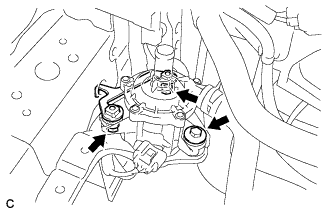
Install the inverter water pump assembly and water pump bracket with the 3 bolts.
- Torque:
- 6.1 N*m { 62 kgf*cm, 54 in.*lbf }
-
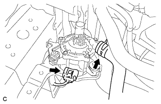
Connect the water hose and connector.
Note
Do not remove the pieces of cloth from the pipes and disconnected hoses until installation to prevent foreign matter from entering the inverter water pump and cooling system.
-
-
INSTALL INVERTER TRAY BRACKET
-
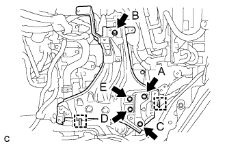
Position the inverter tray bracket as shown in the illustration.
-
Temporarily install bolt B to the inverter tray bracket.
-
Tighten the 5 bolts to the inverter tray bracket in the order the bolt A, bolt C, bolt D, bolt E and bolt B.
- Torque:
- 18 N*m { 184 kgf*cm, 13 ft.*lbf }
-
Connect the 2 clamps to the inverter tray bracket.
-
-
INSTALL INVERTER RESERVE TANK ASSEMBLY
-
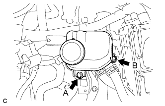
Temporarily install bolt A to the inverter reserve tank assembly.
-
Tighten the 2 bolts to the inverter reserve tank assembly in the order the bolt B and bolt A.
- Torque:
- 10 N*m { 102 kgf*cm, 7 ft.*lbf }
-
-
INSTALL INVERTER WITH CONVERTER ASSEMBLY
Tech Tips
-
ADD COOLANT (for Inverter)
Note
-
Do not reuse the drained coolant because it may contain foreign objects.
-
If the vehicle is driven with air in the inverter cooling system, damage may occur and the following DTCs may be set.
DTC Code Detection Item P0A01-726 Motor Electronics Coolant Temperature Sensor Circuit Range / Performance P0A04-725 Motor Electronics Coolant Temperature Sensor Circuit Intermittent P0A08-264 DC / DC Converter Status Circuit P0A78-284 Drive Motor "A" Inverter Performance P0A78-286 Drive Motor "A" Inverter Performance P0A7A-322 Generator Inverter Performance P0A7A-324 Generator Inverter Performance P0A93-346 Inverter Cooling System Performance P0A94-553 DC / DC Converter Performance P0A94-557 DC / DC Converter Performance P0AEE-277 Motor Inverter Temperature Sensor "A" Circuit Range / Performance P0AF1-276 Drive Motor Inverter Temperature Sensor "A" Circuit Intermittent / Erratic P0BCD-315 Generator Inverter Temperature Sensor Circuit Range / Performance P0BD0-314 Generator Inverter Temperature Sensor Circuit Intermittent / Erratic P0C39-626 DC / DC Converter Temperature Sensor "A" Range / Performance P0C3C-625 DC / DC Converter Temperature Sensor "A" Intermittent / Erratic P0C3E-628 DC / DC Converter Temperature Sensor "B" Range / Performance P0C41-627 DC / DC Converter Temperature Sensor "B" Intermittent / Erratic P0C73-776 Motor Electronics Coolant Pump "A" Control Performance
-
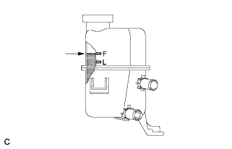
Slowly pour coolant into the reserve tank until it reaches the F line.
Coolant quantity 2.1 liters (2.2 US qts, 1.8 Imp. qts.) -
When using the intelligent tester:
-
Connect the intelligent tester to the DLC3.
-
Turn the power switch on (IG).
-
On the intelligent tester, enter the following menus: Powertrain / Hybrid Control / Active Test / Activate the Water Pump.
-
Keep the coolant at the F line in the reserve tank to compensate for the drop in coolant level when the air bleeds.
Standard Air bleeding from the inverter cooling system is completed when the noise made by the water pump becomes smaller and the circulation of coolant in the reserve tank improves. Tech Tips
Loud noise made by the water pump and poor circulation of coolant in the reserve tank indicates that there is air in the cooling system.
-
-
When not using the intelligent tester:
-
Turn the power switch on (READY). [*1]
-
Turn the power switch off and add coolant to the F line because the coolant level drops as the air bleeds. [*2]
Note
-
Be sure to turn the power switch off before adding SLLC.
-
Do not work on the components in the engine compartment while the vehicle is in the READY-on state because the engine is in intermittent operation.
-
-
Repeat steps [*1] and [*2] until air bleeding from the cooling system is completed.
Standard Air bleeding from the inverter cooling system is completed when the noise made by the water pump becomes smaller and the circulation of coolant in the reserve tank improves. Tech Tips
Loud noise made by the water pump and poor circulation of coolant in the reserve tank indicates that there is air in the cooling system.
-
-
After the air is completely bled from the cooling system, tighten the reserve tank cap.
-
Add coolant to the F line of the reserve tank.
-
-
INSPECT FOR COOLANT LEAK (for Inverter)
-
Remove the reserve tank cap.
CAUTION:
To avoid the danger of being burned, do not remove the reserve tank cap while the coolant for the inverter is still hot.
-
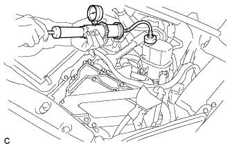
Install the radiator cap tester.
-
Pump the radiator cap tester to 122 kPa (1.2 kgf/ cm2, 17.7 psi), and then check that the pressure does not drop.
Tech Tips
If the pressure drops, check the hoses, radiator, water pump, inverter with converter, and hybrid vehicle transaxle assembly for leaks.
-
Reinstall the reserve tank cap.
-
-
INSTALL NO. 1 ENGINE UNDER COVER
-
INSTALL FRONT SPOILER COVER (w/ Front Spoiler)
-
INSTALL ENGINE UNDER COVER