HV BATTERY INSTALLATION

-
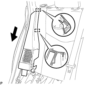
INSTALL NO. 2 HYBRID BATTERY PACK WIRE
-
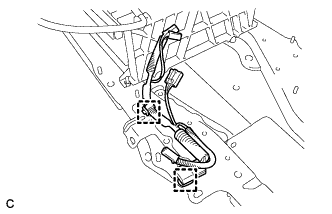
Connect the 2 clamps and No. 2 hybrid battery pack wire.
-
-
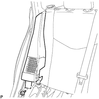
INSTALL NO. 1 HYBRID BATTERY PACKING
CAUTION:
Be sure to wear insulated gloves and protective goggles.
-
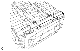
Install the No. 1 hybrid battery packing with the 2 clamps.
-
-
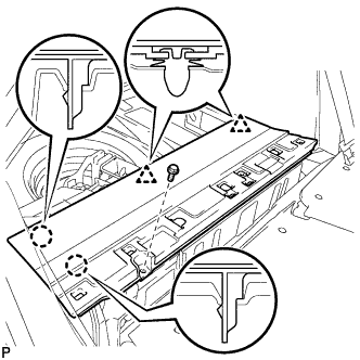
INSTALL UPPER HYBRID BATTERY COVER SUB-ASSEMBLY
CAUTION:
Be sure to wear insulated gloves and protective goggles.
-
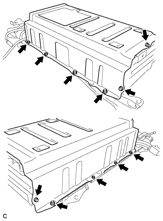
Install the battery cover and No. 1 hybrid battery shield sub-assembly with the 3 bolts and 8 nuts.
- Torque:
- 7.5 N*m { 76 kgf*cm, 66 in.*lbf }
-
-
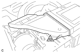
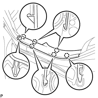
INSTALL NO. 1 HYBRID BATTERY COVER INTAKE DUCT
-
Install the No. 1 hybrid battery cover intake duct with the 2 clips.
-
-
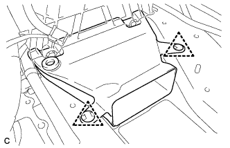
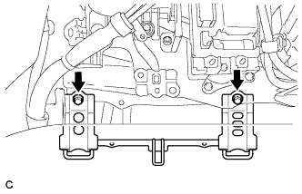
INSTALL NO. 4 HYBRID VEHICLE BATTERY CARRIER BRACKET SUB-ASSEMBLY
CAUTION:
Wear insulated gloves.
-
Install the HV battery thermistor to the No. 4 hybrid vehicle battery carrier bracket sub-assembly.
-
Install the No. 4 hybrid vehicle battery carrier bracket sub-assembly with the 3 bolts.
- Torque:
- 7.5 N*m { 76 kgf*cm, 66 in.*lbf }
-
Connect the 3 wire harness clamps.
-
-
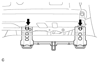
INSTALL NO. 1 HYBRID VEHICLE BATTERY CARRIER BRACKET SUB-ASSEMBLY
CAUTION:
Wear insulated gloves.
-
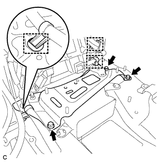
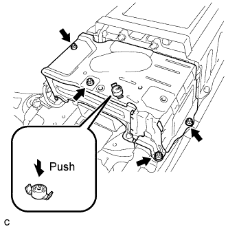
Install the No. 1 hybrid vehicle battery carrier bracket sub-assembly with the 3 nuts.
- Torque:
- 7.5 N*m { 76 kgf*cm, 66 in.*lbf }
-
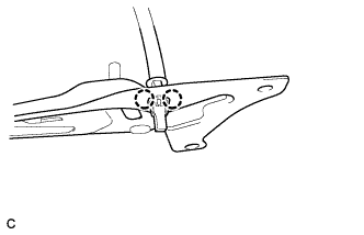
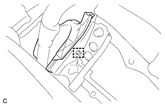
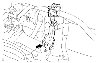
Install the battery cover lock striker, then push the button to lock it.
-
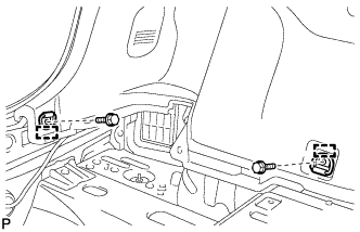
Install the electric vehicle battery plug assembly with the bolt as shown in the illustration.
- Torque:
- 7.5 N*m { 76 kgf*cm, 66 in.*lbf }
-
Connect the connector.
Note
The connector should be connected securely.
-
-
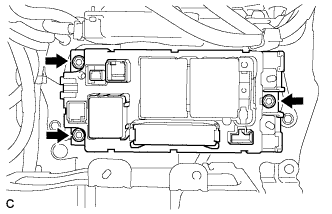
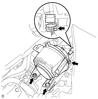
INSTALL BATTERY SMART UNIT
CAUTION:
Wear insulated gloves.
-
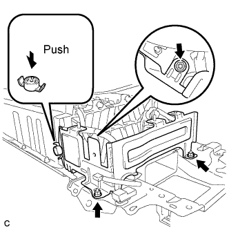
Install the battery smart unit with the 2 bolts.
- Torque:
- 7.5 N*m { 76 kgf*cm, 66 in.*lbf }
-
Connect the 3 connectors.
Note
The connectors should be connected securely.
-
-
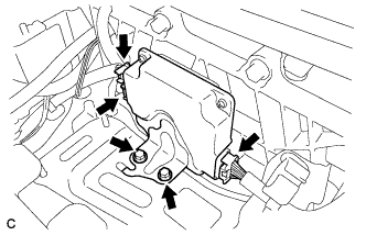
INSTALL HYBRID BATTERY JUNCTION BLOCK
-
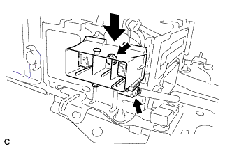
Install the hybrid battery junction block with the 3 nuts.
- Torque:
- 7.5 N*m { 76 kgf*cm, 66 in.*lbf }
-
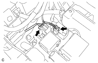
Connect the 2 connectors to the hybrid battery junction block.
Note
The connectors should be connected securely.
-
Connect the 2 connectors to the hybrid battery junction block.
Note
The connectors should be connected securely.
-
-
INSTALL HV BATTERY ASSEMBLY
CAUTION:
Wear insulated gloves.
-
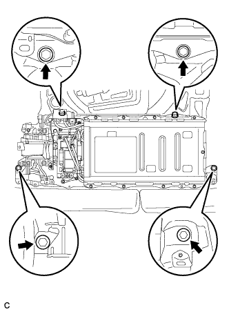
Install the HV battery to the vehicle with the 4 bolts.
- Torque:
- 19 N*m { 194 kgf*cm, 14 ft.*lbf }
-
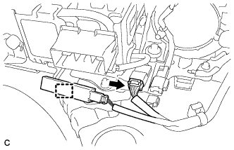
Connect the connector and electrical key oscillator clamp.
-
-
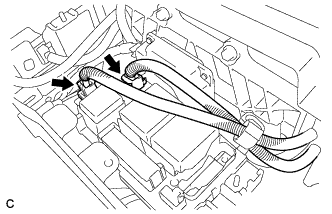
INSTALL FRAME WIRE
CAUTION:
Wear insulating gloves.
-
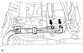
Install the frame wire on the hybrid battery junction block assembly with the 2 nuts.
- Torque:
- 9.0 N*m { 92 kgf*cm, 80 in.*lbf }
Note
-
Make sure that the ends of the frame wire are not crossed over each other.
-
Be sure to connect the frame wires to the correct terminals.
-
Connect the clamp and frame wire.
-
-
CHECK HIGH VOLTAGE CABLE CONNECTION CONDITION
CAUTION:
Wear insulated gloves and protective goggles.
-
Check that each wire harness is being installed securely.
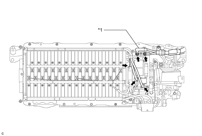
Text in Illustration *1 Frame Wire - - Note
-
Make sure that the end of the frame wire are not crossover each other.
-
Be sure to connect the frame wire to the correct terminals as shown in the illustration.
-
The connectors should be connected securely.
-
The nuts should be fastened securely.
-
Make sure that the 4 plastic covers are engaged securely.
-
-
-
INSTALL CHILD RESTRAINT SEAT ANCHOR BRACKET SUB-ASSEMBLY LH
-
Install the child restraint seat anchor bracket sub-assembly LH with the 2 bolts.
- Torque:
- 20 N*m { 200 kgf*cm, 14 ft.*lbf }
-
-
INSTALL CHILD RESTRAINT SEAT ANCHOR BRACKET SUB-ASSEMBLY RH
-
Install the child restraint seat anchor bracket sub-assembly RH with the 2 bolts.
- Torque:
- 20 N*m { 200 kgf*cm, 14 ft.*lbf }
-
Connect the wire harness protector clamp.
-
-
INSTALL NO. 7 HYBRID VEHICLE BATTERY UPPER CARRIER BRACKET
-
Install the No. 7 hybrid battery upper carrier bracket with the bolt.
- Torque:
- 7.5 N*m { 76 kgf*cm, 66 in.*lbf }
-
-
INSTALL BATTERY COOLING BLOWER ASSEMBLY
Note
-
Be sure not to touch the fan part of the battery cooling blower assemblies.
-
Do not lift the battery cooling blower assemblies using the wire harness.
-
Install the battery cooling blower assembly with the 2 bolts and nut
- Torque:
- 7.5 N*m { 76 kgf*cm, 66 in.*lbf }
-
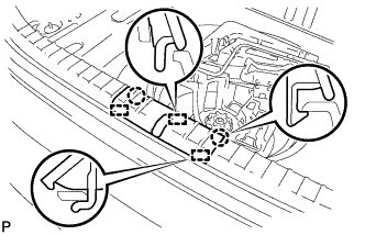
Connect each battery cooling blower assembly connector and clamp.
-
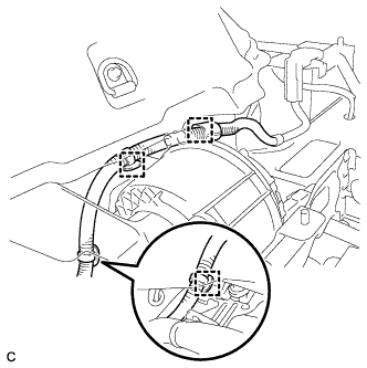
Connect the 3 wire harness clamps.
-
-
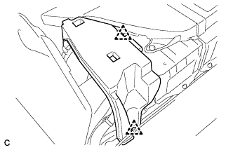
INSTALL NO. 1 HYBRID BATTERY INTAKE DUCT
Note
Ensure that the duct is installed securely.
-
Install the No. 1 hybrid battery intake duct with the 2 clips.
-
-
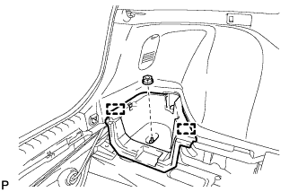
INSTALL UPPER HYBRID BATTERY COVER SUB-ASSEMBLY
-
Install the upper hybrid battery cover sub-assembly with the 4 nuts.
- Torque:
- 7.5 N*m { 76 kgf*cm, 66 in.*lbf }
-
Install the battery cover lock striker, then push the button to lock.
-
-
INSTALL NO. 1 HYBRID BATTERY EXHAUST DUCT
-
Insert the No. 1 hybrid battery exhaust duct with the clip.
Note
Ensure that the duct is installed securely.
-
-
INSTALL REAR FLOOR BOARD SPACER
-
Install the rear floor board spacer with the 2 clips.
-
-
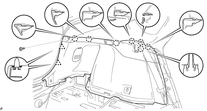
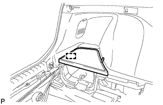
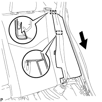
INSTALL DECK TRIM SIDE PANEL ASSEMBLY LH
-
Connect the connector.
-
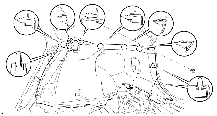
Engage the 7 claws and 2 clips.
-
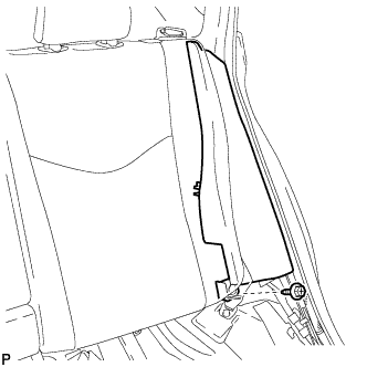
Install the deck trim side panel assembly LH with the screw.
-
-
INSTALL TONNEAU COVER HOLDER CAP (for LH Side)
-
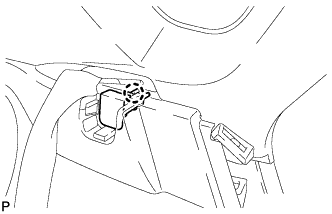
Engage the claw to install the tonneau cover holder cap.
-
-
INSTALL LUGGAGE HOLD BELT STRIKER ASSEMBLY (for LH Side)
-
Engage the 2 guides.
-
Install the 2 luggage hold belt striker assemblies with the 2 bolts.
-
-
INSTALL DECK TRIM SIDE PANEL ASSEMBLY RH
-
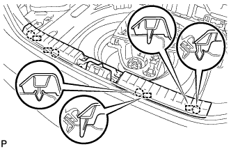
Engage the 7 claws and 2 clips.
-
Install the deck trim side panel assembly RH with the screw.
-
-
REMOVE TONNEAU COVER HOLDER CAP (for RH Side)
Tech Tips
Use the same procedure described for the LH side.
-
INSTALL LUGGAGE HOLD BELT STRIKER ASSEMBLY (for RH Side)
Tech Tips
Use the same procedure described for the LH side.
-
INSTALL REAR DECK TRIM COVER
-
Engage the 4 claws and 4 guides to install the rear deck trim cover.
-
-
INSTALL DECK TRIM SERVICE HOLE COVER
-
Engage the 3 guides.
-
Engage the 2 claws to install the deck trim service hole cover.
-
-
INSTALL DECK FLOOR BOX LH
-
Engage the 2 guides.
-
Install the deck floor box LH with the clip.
-
-
INSTALL REAR NO. 4 FLOOR BOARD
-
Engage the guide to install the rear No. 4 floor board.
-
-
INSTALL REAR SIDE SEAT BACK ASSEMBLY LH
-
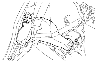
Engage the 2 guides as shown in the illustration.
-
Install the rear side seatback assembly LH with the bolt.
- Torque:
- 18 N*m { 184 kgf*cm, 13 ft.*lbf }
-
-
INSTALL REAR SIDE SEAT BACK ASSEMBLY RH
-
Engage the 2 guides as shown in the illustration.
-
Install the rear side seatback assembly RH with the bolt.
- Torque:
- 18 N*m { 184 kgf*cm, 13 ft.*lbf }
-
-
INSTALL REAR DOOR SCUFF PLATE LH
-
Engage the 7 claws to install the rear door scuff plate LH.
-
-
INSTALL REAR DOOR SCUFF PLATE RH
Tech Tips
Use the same procedure described for the LH side.
-
INSTALL REAR NO. 1 FLOOR BOARD
-
Engage the 2 claws and 2 clips.
-
Install the rear No. 1 floor board with the bolt.
-
-
INSTALL REAR NO. 2 FLOOR BOARD SUB-ASSEMBLY
-

Engage the claw and 2 clips to install the rear No. 2 floor board sub-assembly.
-
-
INSTALL REAR NO. 1 FLOOR BOARD SUB-ASSEMBLY
-
Engage the 2 claws and 2 clips to install the rear No. 1 floor board sub-assembly.
-
-
INSTALL REAR SEAT CUSHION ASSEMBLY
-
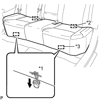
Text in Illustration *1 100 mm (3.94 in.) or less *2 Guide *3 Hook Engage the 2 guides of the seat cushion to the seatback.
-
Engage the 2 front hooks of the seat cushion to the vehicle body.
Note
When installing the seat cushion, make sure that the seat belt buckle is not under the seat cushion.
Tech Tips
Confirm that the seat cushion is firmly installed.
-
-
INSTALL TONNEAU COVER ASSEMBLY (w/ Tonneau Cover)
-
Install the tonneau cover assembly.
-
-
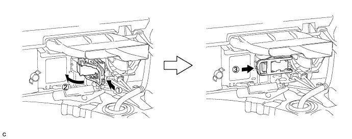
INSTALL SERVICE PLUG GRIP
CAUTION:
Wear insulating gloves.
Note
Before connecting the service plug, check that no parts and tools remain and that the high voltage terminals and connectors are connected securely.
-
Wear insulated gloves and install the service plug grip in the order shown in the illustration.
-
Rotate the handle of the service plug grip 90° toward the battery and slide it in the direction shown by the arrow until a click sound is heard.
-
-
CONNECT CABLE TO NEGATIVE BATTERY TERMINAL
Note
When disconnecting the cable, some systems need to be initialized after the cable is reconnected Click here.
-
INSTALL REAR NO. 3 FLOOR BOARD
-

Engage the 2 guides to install the rear No. 3 floor board.
-
-
INSTALL REAR DECK FLOOR BOX
-
Install the rear deck floor box.
-
-
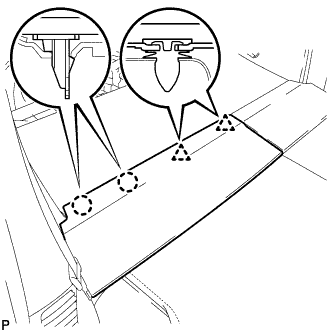
INSTALL REAR NO. 2 FLOOR BOARD
-

Engage the 3 guides <A>.
-
Engage the 2 guides <B> and install the rear No. 2 floor board as shown in the illustration.
-