INVERTER CURRENT SENSOR DISASSEMBLY

Tech Tips
For the disassembly procedure of the inverter with converter assembly, refer to the disassembly procedure of the MG control computer with bracket sub-assembly. Click here
-
REMOVE INVERTER CURRENT SENSOR SUB-ASSEMBLY
Tech Tips
The number of clamps used to engage the wire harnesses of the inverter current sensor sub-assembly varies depending on the part number of the inverter with converter assembly. Confirm the part number before performing work.
Text in Illustration *A For inverter with converter assembly with part number G9200-47140, G9200-47141, G9200-47180 or G9200-47181 *B For inverter with converter assembly with part number other than G9200-47140, G9200-47141, G9200-47180 or G9200-47181
-
Apply protective tape to the inverter terminal with sensor sub-assembly as shown in the illustration.
Note
Use non-residue type tape.
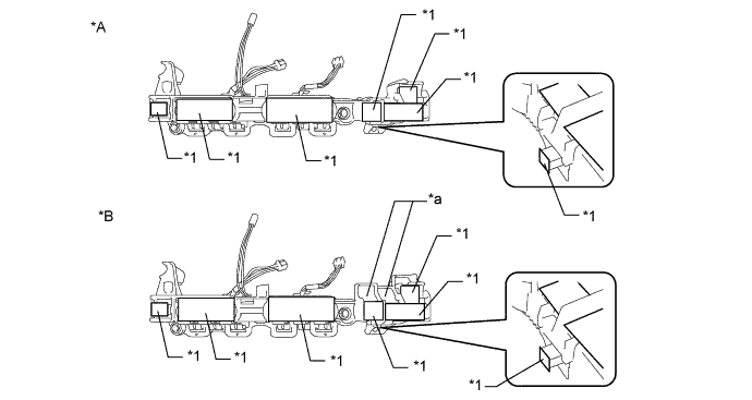
Text in Illustration *A Type 1 *B Type 2 *1 Protective Tape - - *a Terminal Tray - - -
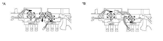
Disengage the 2 wire harnesses of the inverter current sensor sub-assembly from each clamp as shown in the illustration.
Tech Tips
The number of clamps used to engage the wire harness varies depending on the type of inverter with converter assembly. Confirm the type before performing work.
Text in Illustration *A For inverter with converter assembly with part number G9200-47140, G9200-47141, G9200-47180 or G9200-47181 *B For inverter with converter assembly with part number other than G9200-47140, G9200-47141, G9200-47180 or G9200-47181 -
Text in Illustration *A Type 1 *B Type 2 *a Terminal Tray Remove the 2 bolts and inverter current sensor sub-assembly.
Note
Do not touch the bus-bars.
-
-
REMOVE INVERTER WIRE SUB-ASSEMBLY
-
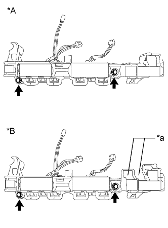
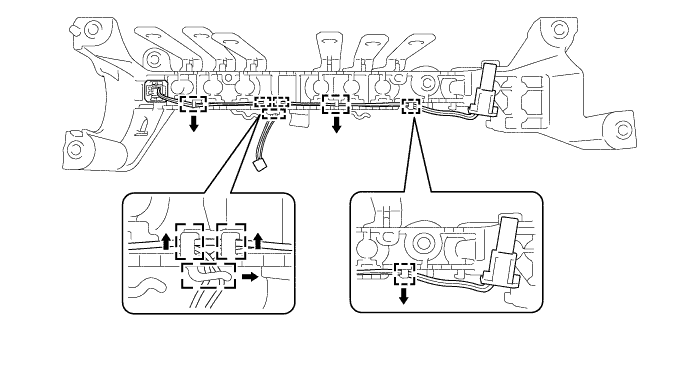
Disengage the wire harness of the inverter wire sub-assembly from each clamp as shown in the illustration.
Note
Do not pull the wire harness excessively.
Text in Illustration *A Type 1 *B Type 2 *a Terminal Tray - - -
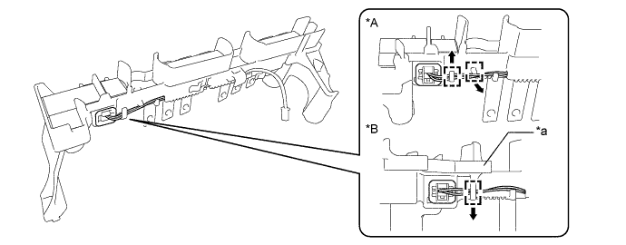
Using a screwdriver, disengage the 2 claws while lightly pushing in the protruding part of the interlock connector (A) as shown in the illustration to disconnect it.
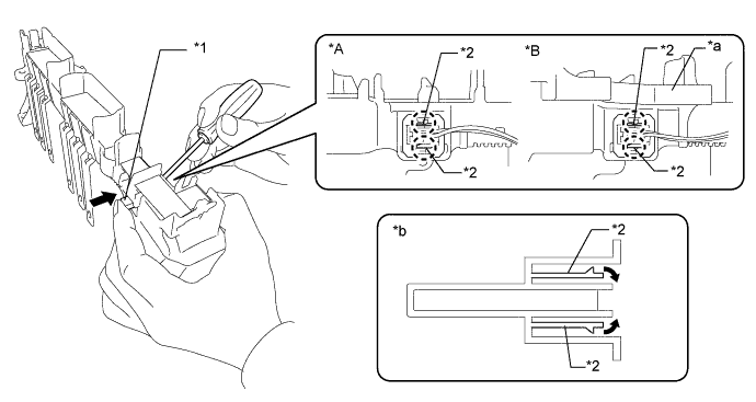
Text in Illustration *A Type 1 *B Type 2 *1 Inter Lock Connector A *2 Claw *a Terminal Tray *b Cross Section (Inter Lock Connector A) -
Disengage the wire harness of the inverter wire sub-assembly from the 6 clamps.
-
Using a screwdriver, disengage the 2 claws while lightly pushing in the protruding part of the interlock connector (B) as shown in the illustration to disconnect it and remove the inverter wire sub-assembly.
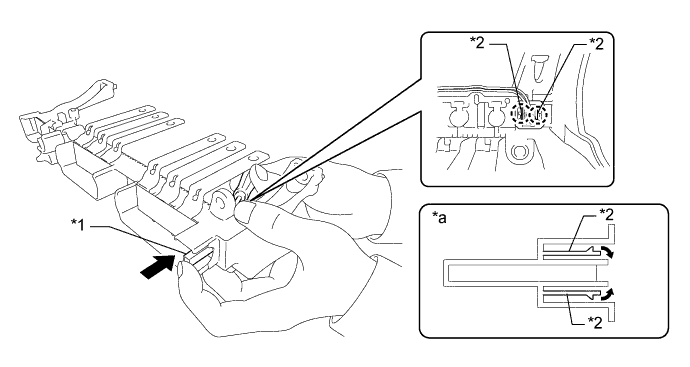
Text in Illustration *1 Inter Lock Connector B *2 Claw *a Cross Section (Inter Lock Connector B) - -
-