HYBRID BATTERY SYSTEM, Diagnostic DTC:P0AC0-123

| DTC Code | DTC Name |
|---|---|
| P0AC0-123 | Hybrid Battery Pack Current Sensor Circuit Range / Performance |
DESCRIPTION
Refer to the Description for DTC P0ABF-123 Click here.
| DTC No. | DTC Detection Condition | Trouble Area |
|---|---|---|
| P0AC0-123 | When the battery current sensor is abnormal (1 or 2 trip detection) |
|
INSPECTION PROCEDURE
CAUTION:
-
Before inspecting the high-voltage system, take safety precautions to prevent electrical shocks, such as wearing insulated gloves and removing the service plug grip. After removing the service plug grip, put it in your pocket to prevent other technicians from accidentally reconnecting it while you are working on the high-voltage system.
-
After disconnecting the service plug grip, wait for at least 10 minutes before touching any of the high-voltage connectors or terminals.
Tech Tips
At least 10 minutes is required to discharge the high-voltage capacitor inside the inverter with converter assembly.
Note
After the power switch is turned off, the display and navigation module display (HDD navigation system) records various types of memory and settings. As a result, after turning the power switch off, make sure to wait at least 60 seconds before disconnecting the cable from the negative (-) battery terminal.
PROCEDURE
-
CHECK DTC OUTPUT (HV)
-
Connect the intelligent tester to the DLC3.
-
Turn the power switch on (IG).
-
Enter the following menus: Powertrain / Hybrid Control / DTC.
-
Read output DTCs Click here.
Result Result Proceed to Only DTC P0AC0-123 is output or DTC P0AC0-123 and DTCs other than those in the following table are output. A Any of the DTCs in the following table are output at the same time. B DTC No. Relevant Diagnosis P0A95-123 High Voltage Fuse P0ABF-123 Hybrid Battery Pack Current Sensor Circuit P0AC1-123 Hybrid Battery Pack Current Sensor "A" Circuit Low P0AC2-123 Hybrid Battery Pack Current Sensor "A" Circuit High P0AFC-123 Hybrid Battery Pack Sensor Module P0B3D-123, P0B42-123, P0B47-123, P0B4C-123, P0B51-123, P0B56-123, P0B5B-123, P0B60-123, P0B65-123, P0B6A-123, P0B6F-123, P0B74-123, P0B79-123, P0B7E-123, P0B83-123 Hybrid Battery Voltage Sensor "A - O" Circuit Low -
Turn the power switch off.
-
Disconnect the intelligent tester from the DLC3.
B 
GO TO DTC CHART Click here
A 
-
-
READ VALUE USING INTELLIGENT TESTER
-
Connect the intelligent tester to the DLC3.
-
Turn the power switch on (IG).
Note
Do not turn the power switch on (READY).
-
Enter the following menus: Powertrain / Hybrid Control / Data List / Battery block Vol -V01 to V14.
Note
Select "Battery block Vol -V01 to V14" only. (Do not select any other Data List items.)
-
Check the voltage of each "Battery block Vol" of "Battery block Vol -V01 to V14" in the Data List with the power switch on (IG).
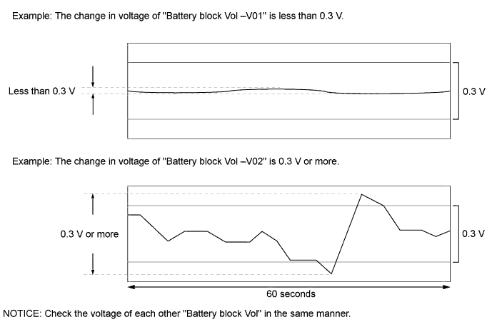
Specified Condition Any "Battery block Vol" changes by 0.3 V or more, 60 seconds after the power switch is turned on (IG). (the difference between the maximum and minimum voltage is 0.3 V or more.) Result Result Proceed to The change in voltage of any "Battery block Vol" is 0.3 V or more. A Other than above. B
B
REPLACE HYBRID BATTERY JUNCTION BLOCK Click here
A 
REPLACE BATTERY SMART UNIT Click here
-