HV BATTERY REMOVAL

-
PRECAUTION
Tech Tips
-
READ OUTPUT DTC
-
Check for DTCs Click here.
Note
Check for DTCs and confirm that P0AA6 (Hybrid Battery Voltage System Isolation Fault) is not output before doing removal or installation inside the battery. If this DTC is output, perform troubleshooting fir this DTC first.
-
-
REMOVE REAR NO. 2 FLOOR BOARD
-

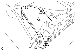
Disengage the 2 guides <A> as shown in the illustration.
-
Disengage the 3 guides <B> and remove the rear No. 2 floor board.
-
-
REMOVE REAR DECK FLOOR BOX
-
Remove the rear deck floor box.
-
-
REMOVE REAR NO. 3 FLOOR BOARD
-

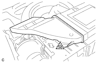
Disengage the 2 guides and remove the rear No. 3 floor board.
-
-
DISCONNECT CABLE FROM NEGATIVE BATTERY TERMINAL
Note
When disconnecting the cable, some systems need to be initialized after the cable is reconnected Click here.
-
REMOVE SERVICE PLUG GRIP
CAUTION:
-
Wear insulating gloves.
-
Remove the service plug grip to interrupt the high voltage circuit at the time of inspection or repair.
-
Keep the removed service plug grip in your pocket to prevent other technicians from accidentally reconnecting it while you are servicing the vehicle.
-
All the high voltage wiring connectors are colored in orange.
-
Wear insulating gloves and remove the service plug grip after sliding up the lever of the service plug grip as shown in the illustration.
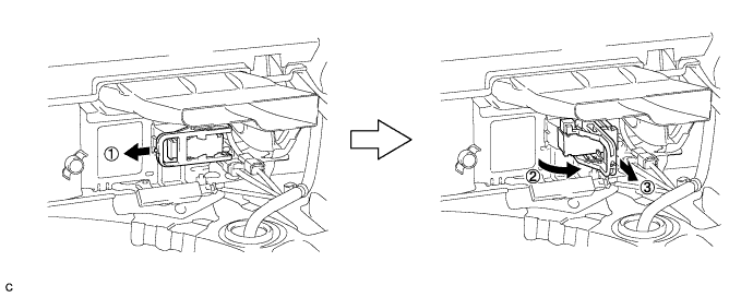
CAUTION:
-
Keep the removed service plug grip in your pocket to prevent other technicians from accidentally reconnecting it while you are servicing the vehicle.
-
After removing the service plug grip, do not touch the high voltage connectors or terminals for 10 minutes.
Tech Tips
Waiting for at least 10 minutes is required to discharge the high-voltage capacitor inside the inverter with converter assembly.
-
-
-
REMOVE INVERTER TERMINAL COVER
CAUTION:
Wear insulating gloves.
-
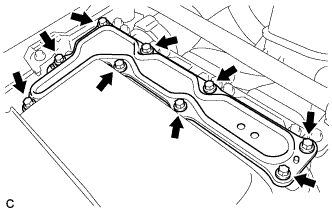
Remove the 9 bolts and inverter terminal cover.
Note
Make sure to pull the inverter terminal cover straight up, as a connector is connected to the bottom of the cover.
-
-
CHECK TERMINAL VOLTAGE
CAUTION:
Wear insulating gloves.
Note
Do not allow any foreign objects or water to enter the inverter with converter assembly.
-
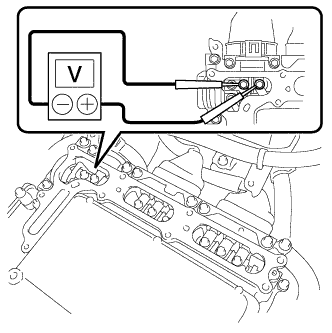
Using a voltmeter, measure the voltage between the terminals of the 2 phase connectors.
Standard voltage 0 V Tech Tips
Use measuring range of DC 750 V or more on the voltmeter.
-
-
INSTALL INVERTER TERMINAL COVER
CAUTION:
Wear insulating gloves.
Note
-
Make sure that the interlock is fully engaged.
-
Do not allow any foreign objects or water to enter the inverter with converter assembly.
-
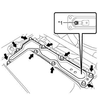
Text in Illustration *1 Interlock Install the inverter terminal cover with the 9 bolts to the inverter with converter assembly.
- Torque:
- 11 N*m { 112 kgf*cm, 8 ft.*lbf }
-
-
REMOVE TONNEAU COVER ASSEMBLY (w/ Tonneau Cover)
-
Remove the tonneau cover assembly.
-
-
REMOVE REAR SEAT CUSHION ASSEMBLY
-
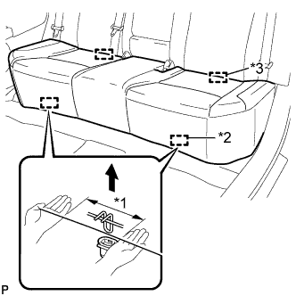
Text in Illustration *1 100 mm (3.94 in.) or less *2 Hook *3 Guide Disengage the 2 front hooks of the seat cushion from the vehicle body as shown in the illustration.
Note
Follow the instructions below carefully as the cushion frame deforms easily.
-
Choose a hook to detach first. Place your hands near the hook as shown in the illustration. Then lift the seat cushion to detach the hook.
-
Repeat the above procedure for the other hook.
-
-
Disengage the 2 guides of the seat cushion from the seatback.
-
Remove the rear seat cushion assembly.
-
-
REMOVE REAR NO. 1 FLOOR BOARD SUB-ASSEMBLY
-
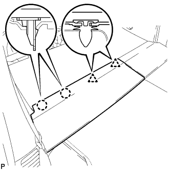
Disengage the 2 claws and 2 clips, and remove the rear No. 1 floor board sub-assembly.
-
-
REMOVE REAR NO. 2 FLOOR BOARD SUB-ASSEMBLY
-

Disengage the claw and 2 clips, and remove the rear No. 2 floor board sub-assembly.
-
-
REMOVE REAR NO. 1 FLOOR BOARD
-
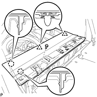
Remove the bolt.
-
Disengage the 2 claws and 2 clips, and remove the rear No. 1 floor board.
-
-
REMOVE REAR DOOR SCUFF PLATE LH
-
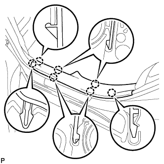
Disengage the 7 claws and remove the rear door scuff plate LH.
-
-
REMOVE REAR DOOR SCUFF PLATE RH
Tech Tips
Use the same procedure described for the LH side.
-
REMOVE REAR SIDE SEAT BACK ASSEMBLY LH
-
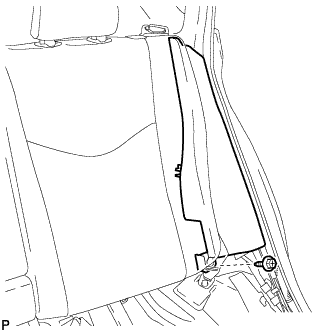
Remove the bolt.
-
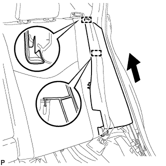
Disengage the 2 guides and remove the rear side seatback assembly LH as shown in the illustration.
-
-
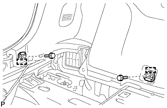
REMOVE REAR SIDE SEAT BACK ASSEMBLY RH
-
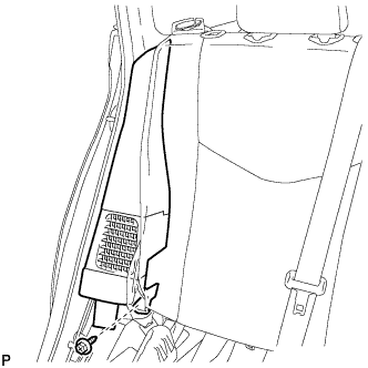
Remove the bolt.
-
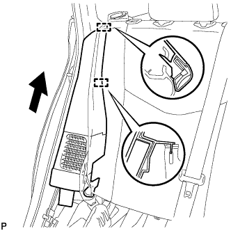
Disengage the 2 guides and remove the rear side seatback assembly RH as shown in the illustration.
-
-
REMOVE REAR NO. 4 FLOOR BOARD
-
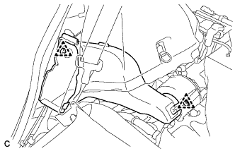
Disengage the guide and remove the rear No. 4 floor board.
-
-
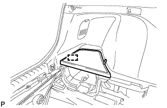
REMOVE DECK FLOOR BOX LH
-
Remove the clip.
-
Disengage the 2 guides and remove the deck floor box LH.
-
-
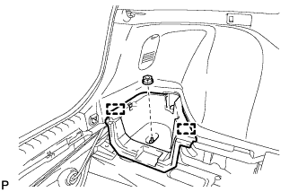
REMOVE DECK TRIM SERVICE HOLE COVER
-
Disengage the 2 claws and 3 guides, and remove the deck trim service hole cover.
-
-
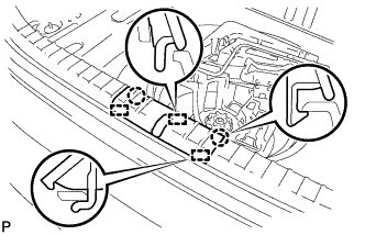
REMOVE REAR DECK TRIM COVER
-
Disengage the 4 claws and 4 guides, and remove the rear deck trim cover.
-
-
REMOVE LUGGAGE HOLD BELT STRIKER ASSEMBLY (for LH Side)
-
Remove the 2 bolts.
-
Disengage each guide and remove the 2 luggage hold belt striker assemblies.
-
-
REMOVE TONNEAU COVER HOLDER CAP (for LH Side)
-
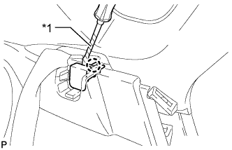
Text in Illustration *1 Protective Tape Using a screwdriver, disengage the claw and remove the tonneau cover holder cap.
Tech Tips
Tape the screwdriver tip before use.
-
-
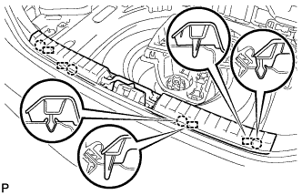
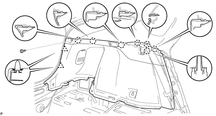
REMOVE DECK TRIM SIDE PANEL ASSEMBLY LH
-
Remove the screw.
-
Disengage the 7 claws and 2 clips.
-
Disconnect the connector and remove the deck trim side panel assembly LH.
-
-
REMOVE TONNEAU COVER HOLDER CAP (for RH Side)
Tech Tips
Use the same procedure described for the LH side.
-
REMOVE LUGGAGE HOLD BELT STRIKER ASSEMBLY (for RH Side)
Tech Tips
Use the same procedure described for the LH side.
-
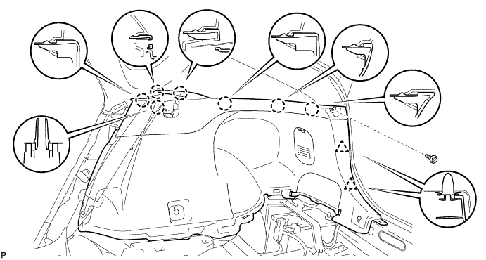
REMOVE DECK TRIM SIDE PANEL ASSEMBLY RH
-
Remove the screw.
-
Disengage the 7 claws and 2 clips, and remove the deck trim side panel assembly RH.
-
-
REMOVE REAR FLOOR BOARD SPACER
-
Remove the 2 clips and rear floor board spacer.
-
-
REMOVE NO. 1 HYBRID BATTERY EXHAUST DUCT
-
Remove the clip and No. 1 hybrid battery exhaust duct.
-
-
REMOVE UPPER HYBRID BATTERY COVER SUB-ASSEMBLY
CAUTION:
Be sure to wear insulated gloves and protective goggles.
-
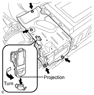
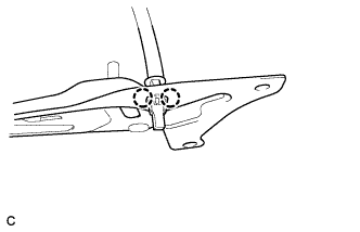
Using the service plug grip, remove the battery cover lock striker.
Tech Tips
Insert the projection part of the service plug grip, and turn the button of the battery cover lock striker counterclockwise, and release the lock.
-
Remove the 4 nuts and upper hybrid battery cover sub-assembly.
-
-
REMOVE NO. 1 HYBRID BATTERY INTAKE DUCT
-
Remove the 2 clips and No. 1 hybrid battery intake duct.
-
-
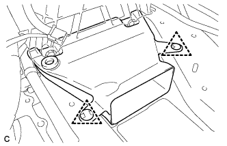
REMOVE BATTERY COOLING BLOWER ASSEMBLY
Note
-
Be sure not to touch the fan part of the battery cooling blower assemblies.
-
Do not lift the battery cooling blower assemblies using the wire harness.
-
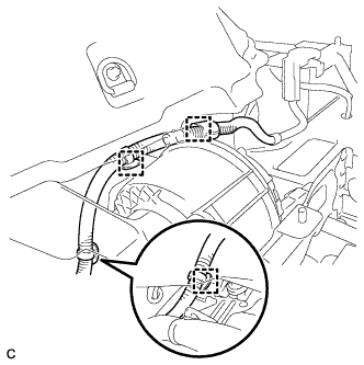
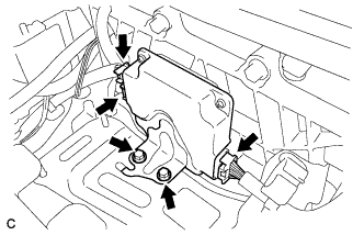
Disconnect the 3 wire harness clamps.
-
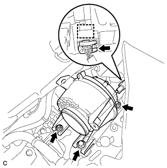
Disconnect the battery cooling blower assembly connector and clamp.
-
Remove the 2 bolts, nut and battery cooling blower assembly.
-
-
REMOVE NO. 7 HYBRID VEHICLE BATTERY UPPER CARRIER BRACKET
-
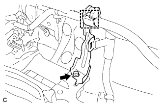
Disconnect the wire harness clamp.
-
Remove the bolt and No. 7 hybrid battery upper carrier bracket.
-
-
REMOVE CHILD RESTRAINT SEAT ANCHOR BRACKET SUB-ASSEMBLY LH
-
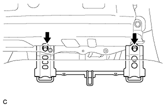
Remove the 2 bolts and child restraint seat anchor bracket sub-assembly LH.
-
-
REMOVE CHILD RESTRAINT SEAT ANCHOR BRACKET SUB-ASSEMBLY RH
-
Disconnect the wire harness protector clamp.
-
Remove the 2 bolts and child restraint seat anchor bracket sub-assembly RH.
-
-
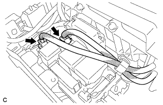
REMOVE FRAME WIRE
CAUTION:
-
Wear insulating gloves.
-
Insulate the removed terminals with insulating tape.
-
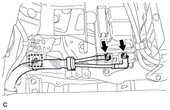
Remove the 2 nuts, then disconnect the frame wire from the hybrid battery junction block assembly.
-
Disconnect the clamp and frame wire.
-
-
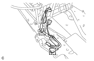
REMOVE HV BATTERY ASSEMBLY
CAUTION:
Wear insulating gloves.
-
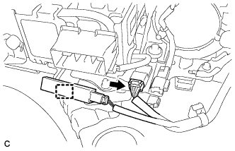
Disconnect the connector and electrical key oscillator clamp.
-
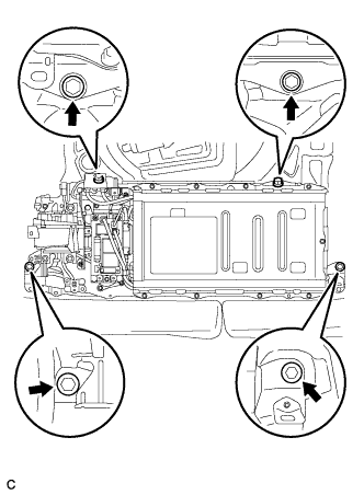
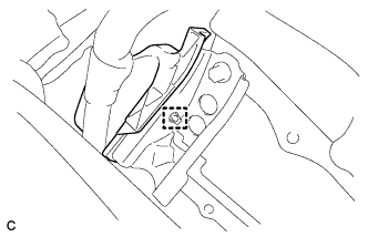
Remove the 4 bolts shown in the illustration.
-
Remove the HV battery.
-
-
REMOVE HYBRID BATTERY JUNCTION BLOCK
CAUTION:
Wear insulating gloves.
-
Disconnect the 2 connectors from the hybrid battery junction block.
-
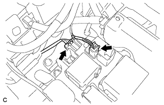
Disconnect the 2 connectors from the hybrid battery junction block.
-
Remove the 3 nuts and hybrid battery junction block.
-
-
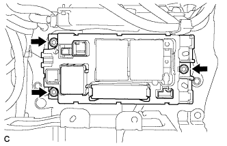
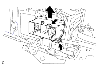
REMOVE BATTERY SMART UNIT
CAUTION:
Wear insulating gloves.
-
Disconnect the 3 connectors.
-
Remove the 2 nuts and battery smart unit.
-
-
REMOVE NO. 1 HYBRID VEHICLE BATTERY CARRIER BRACKET SUB-ASSEMBLY
CAUTION:
Wear insulating gloves.
-
Disconnect the connector.
-
Remove the bolt and EV battery plug as shown in the illustration.
-
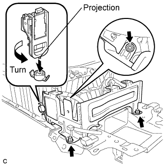
Using the service plug grip, remove the battery cover lock striker.
Tech Tips
Insert the projection part of the service plug grip, and turn the button of the battery cover lock striker counterclockwise, and release the lock.
-
Remove the 3 nuts and No. 1 hybrid vehicle battery carrier bracket sub-assembly.
-
-
REMOVE NO. 4 HYBRID VEHICLE BATTERY CARRIER BRACKET SUB-ASSEMBLY
CAUTION:
Wear insulating gloves.
-
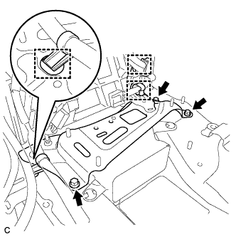
Disconnect the 3 wire harness clamps.
-
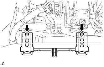
Remove the 3 bolts and No. 4 hybrid vehicle battery carrier bracket sub-assembly.
-
Disengage the 2 claws and remove the HV battery thermistor.
-
-
REMOVE NO. 1 HYBRID BATTERY COVER INTAKE DUCT
-
Remove the 2 clips and No. 1 hybrid battery cover intake duct.
-
-
REMOVE UPPER HYBRID BATTERY COVER SUB-ASSEMBLY
CAUTION:
Be sure to wear insulated gloves and protective goggles.
-
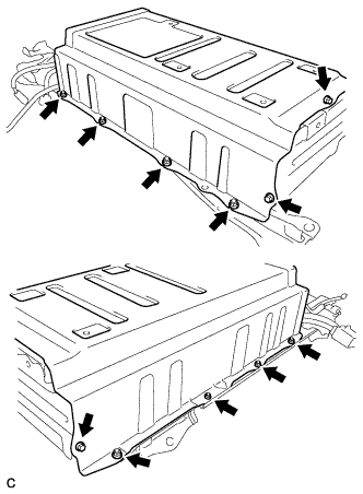
Remove the 3 bolts, 8 nuts and battery cover with the No. 1 hybrid battery shield sub-assembly.
-
-
REMOVE NO. 1 HYBRID BATTERY PACKING
CAUTION:
Be sure to wear insulated gloves and protective goggles.
-
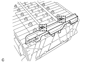
Remove the 2 clamps and No. 1 hybrid battery packing.
-
-
REMOVE NO. 2 HYBRID BATTERY PACK WIRE
-
Disconnect the 2 clamps, then remove the No. 2 hybrid battery pack wire.
-