HYBRID CONTROL SYSTEM, Diagnostic DTC:P324E-788

| DTC Code | DTC Name |
|---|---|
| P324E-788 | MG-ECU Power Relay Intermittent Circuit |
DESCRIPTION
If the inverter with converter assembly (MG ECU) is reset due to a problem with the power source in the inverter, the power management control ECU (HV CPU) will set this DTC.
| DTC No. | INF Code | DTC Detection Condition | Trouble Area |
|---|---|---|---|
| P324E | 788 | Error in reset signal from the inverter assembly power source IC |
|
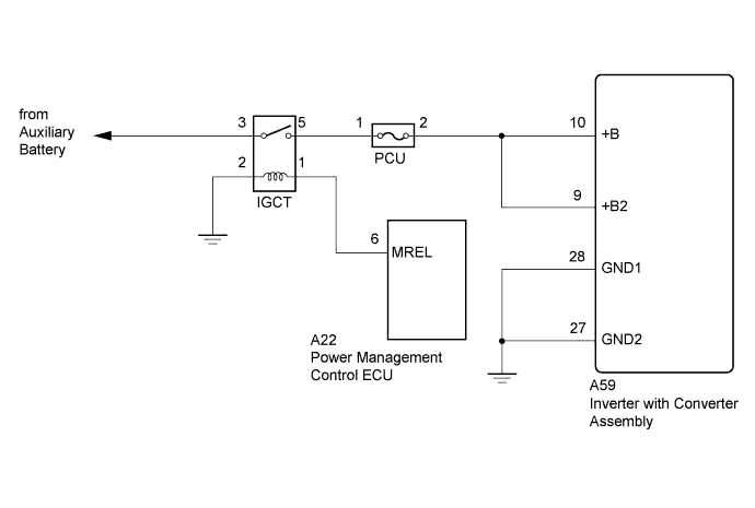
WIRING DIAGRAM
INSPECTION PROCEDURE
CAUTION:
-
Before inspecting the high-voltage system or disconnecting the low voltage connector of the inverter with converter assembly, take safety precautions such as wearing insulated gloves and removing the service plug grip to prevent electrical shocks. After removing the service plug grip, put it in your pocket to prevent other technicians from accidentally reconnecting it while you are working on the high-voltage system.
-
After disconnecting the service plug grip, wait for at least 10 minutes before touching any of the high-voltage connectors or terminals. After waiting for 10 minutes, check the voltage at the terminals in the inspection point in the inverter with converter assembly. The voltage should be 0 V before beginning work.
Tech Tips
Waiting for at least 10 minutes is required to discharge the high-voltage capacitor inside the inverter with converter assembly.
Tech Tips
After the repair, clear the DTCs and perform the following procedure to check that DTCs are not output.
-
Turn the power switch on (IG) and wait for 5 seconds or more.
PROCEDURE
-
CHECK DTC OUTPUT (HV)
-
Connect the intelligent tester to the DLC3.
-
Turn the power switch on (IG).
-
Enter the following menus: Powertrain / Hybrid Control / Trouble Codes.
-
Check if DTCs are output.
Result Result Proceed to Only DTC P324E-788 is output or any DTCs other than U0110-159, 160, 656 or 657 is also output. A U0110-159, 160, 656, 657 are also output. B -
Turn the power switch off.
B 
GO TO DTC CHART Click here
A 
-
-
CHECK CONNECTOR CONNECTION CONDITION (INVERTER WITH CONVERTER ASSEMBLY CONNECTOR)
CAUTION:
Be sure to wear insulated gloves.
-
Check that the service plug grip is not installed.
Note
After removing the service plug grip, do not turn the power switch on (READY), unless instructed by the repair manual because this may cause a malfunction.
Note
Before disconnecting the connector, confirm that it is properly connected by checking that the locking claws are engaged and that the connector does not pull out.
-
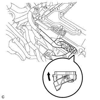
Check the connection of the low voltage connector of the inverter with converter assembly.
OK The connector is connected securely and there are no contact problems. Tech Tips
When connecting the connector, insert it with the locking lever in the raised position. Rotate the lever downward and make sure that the connector is pulled into its socket. When the locking lever is in its fully closed position, a click will be heard as its locking claws engage. After the click is heard, pull up on the connector to confirm that it is properly connected.
NG
CONNECT SECURELY
OK
-
-
CHECK HARNESS AND CONNECTOR (INVERTER WITH CONVERTER ASSEMBLY - IGCT RELAY)
CAUTION:
Be sure to wear insulated gloves.
-
Check that the service plug grip is not installed.
Note
After removing the service plug grip, do not turn the power switch on (READY), unless instructed by the repair manual because this may cause a malfunction.
-
Disconnect connector A59 from the inverter with converter assembly.
-
Remove the IGCT relay from the engine room junction block assembly.
-
Measure the resistance according to the value(s) in the table below.
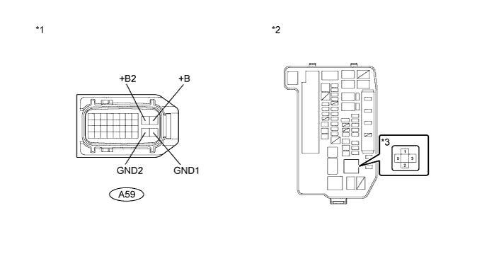
Text in Illustration *1 Front view of wire harness connector
(to Inverter with Converter Assembly)
*2 Engine Room Junction Block Assembly *3 IGCT Relay - - Standard Resistance (Check for open) Tester Connection Switch Condition Specified Condition A59-10 (+B) - 5 (IGCT Relay) Power switch off Below 1 Ω A59-9 (+B2) - 5 (IGCT Relay) Power switch off Below 1 Ω A59-28 (GND1) - Body ground Power switch off Below 1 Ω A59-27 (GND2) - Body ground Power switch off Below 1 Ω -
Install the IGCT relay.
-
Connect the power management control ECU connector.
NG
REPAIR OR REPLACE HARNESS OR CONNECTOR
OK
-
-
CHECK DTC OUTPUT (HV)
-
Connect the intelligent tester to the DLC3.
-
Turn the power switch on (IG).
-
Enter the following menus: Powertrain / Hybrid Control / Trouble Codes.
-
Check if DTCs are output.
Result Result Proceed to Only DTC P0A1A-151, P0A1A-659 or P324E-788 is output. A DTC P0A94-172, P0A94-553 or P0A94-557 is also output. B Other than above. C -
Turn the power switch off.
B 
CLEAR DTC Click here
C
GO TO DTC CHART Click here
A
-
-
CHECK DTC OUTPUT (HV)
-
Connect the intelligent tester to the DLC3.
-
Turn the power switch off and wait for 30 seconds or more.
-
Turn the power switch on (IG) and wait for 5 seconds or more.
-
Turn the power switch on (READY).
-
Enter the following menus: Powertrain / Hybrid Control / Trouble Codes.
-
Check if DTCs are output.
Result Result Proceed to No DTCs are output (not including history DTCs). A Only DTC P0A1A-151, P0A1A-659 or P324E-788 is output. B Other than above. C -
Turn the power switch off.
A
CHECK INVERTER WITH CONVERTER ASSEMBLY Click here
B
CHECK INVERTER WITH CONVERTER ASSEMBLY Click here
C 
GO TO DTC CHART Click here
-
-
CLEAR DTC
-
Connect the intelligent tester to the DLC3.
-
Turn the power switch on (IG).
-
Enter the following menus: Powertrain / Hybrid Control / Trouble Codes.
-
Read and record the DTCs and freeze frame data.
-
Clear DTCs and freeze frame data.
-
Turn the power switch off.
NEXT
-
-
CHECK DTC OUTPUT (HV)
-
Connect the intelligent tester to the DLC3.
-
Turn the power switch on (IG) and wait for 5 seconds or more.
-
Turn the power switch on (READY) and wait for 5 seconds or more.
-
Depress the accelerator pedal with the engine stopped and park (P) selected to start the engine and idle it for 10 seconds or more.
-
Enter the following menus: Powertrain / Hybrid Control / Trouble Codes.
-
Check if DTCs are output.
Result Result Proceed to No DTCs are output. A DTC P0A94-442, P0A94-553, P0A94-557, P3004-800 or P3004-801 is output. A DTCs other than P0A94-442, P0A94-553, P0A94-557, P3004-800 or P3004-801 are output. B -
Turn the power switch off.
B
CHECK INVERTER WITH CONVERTER ASSEMBLY Click here
A
REPLACE POWER MODULE INTELLIGENT TRANSISTOR KIT Click here
-
-
CHECK INVERTER WITH CONVERTER ASSEMBLY
-
Check the installation position of the part No. label on the inverter with converter assembly Click here.
-
Check the part number of the inverter with converter assembly.
Result Result Proceed to Installation Position of Part No. Label Part No. Front - A Top
-
G9200-47140
-
G9200-47141
-
G9200-47180
-
G9200-47181
Other than above. B -
B
REPLACE MG CONTROL COMPUTER Click here
A
REPLACE MG CONTROL COMPUTER AND INVERTER CURRENT SENSOR AND INVERTER WIRE Click here
-
-
CHECK INVERTER WITH CONVERTER ASSEMBLY
-
Check the installation position of the part No. label on the inverter with converter assembly Click here.
-
Check the part number of the inverter with converter assembly.
Result Result Proceed to Installation Position of Part No. Label Part No. Front - A Top
-
G9200-47140
-
G9200-47141
-
G9200-47180
-
G9200-47181
Other than above. B -
B
REPLACE POWER MODULE INTELLIGENT TRANSISTOR KIT AND MG CONTROL COMPUTER Click here
A
REPLACE POWER MODULE INTELLIGENT TRANSISTOR KIT AND MG CONTROL COMPUTER AND INVERTER CURRENT SENSOR AND INVERTER WIRE Click here
-