NAVIGATION SYSTEM (for DVD) Reverse Signal Circuit
DESCRIPTION
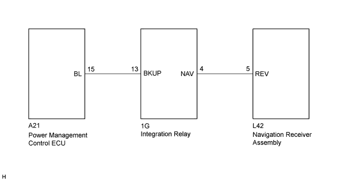
The navigation receiver assembly receives a reverse signal from the power management control ECU via the integration relay to use for adjusting the vehicle position on the navigation display.
WIRING DIAGRAM
INSPECTION PROCEDURE
PROCEDURE
-
INSPECT NAVIGATION RECEIVER ASSEMBLY
-
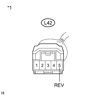
Text in Illustration *1 Front view of wire harness connector
(to Navigation Receiver Assembly)
Disconnect the L42 navigation receiver assembly connector.
-
Measure the voltage according to the value(s) in the table below.
Standard Voltage Tester Connection Condition Specified Condition L42-5 (REV) - Body ground Power switch on (IG)
Shift lever in R
11 to 14 V L42-5 (REV) - Body ground Power switch on (IG)
Shift lever in any position except R
Below 1 V
NG 
CHECK HARNESS AND CONNECTOR (NAVIGATION RECEIVER ASSEMBLY - INTEGRATION RELAY) Click here
OK 
PROCEED TO NEXT SUSPECTED AREA SHOWN IN PROBLEM SYMPTOMS TABLE Click here
-
-
CHECK HARNESS AND CONNECTOR (NAVIGATION RECEIVER ASSEMBLY - INTEGRATION RELAY)
-
Disconnect the L42 navigation receiver assembly connector.
-
Disconnect the 1G integration relay connector.
-
Measure the resistance according to the value(s) in the table below.
Standard Resistance Tester Connection Condition Specified Condition L42-5 (REV) - 1G-4 (NAV) Always Below 1 Ω L42-5 (REV) - Body ground Always 10 kΩ or higher Text in Illustration *1 Front view of wire harness connector
(to Navigation Receiver Assembly)
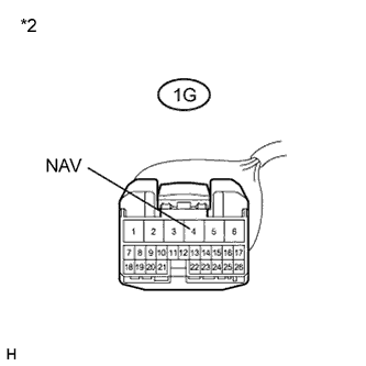
*2 Front view of wire harness connector
(to Integration Relay)
NG 
REPAIR OR REPLACE HARNESS OR CONNECTOR
OK 
-
-
INSPECT INTEGRATION NO.1 RELAY
-
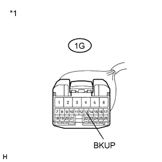
Text in Illustration *1 Front view of wire harness connector
(to Integration Relay)
Disconnect the 1G integration relay connector.
-
Measure the voltage according to the value(s) in the table below.
Standard Voltage Tester Connection Condition Specified Condition 1G-13 (BKUP) - Body ground Power switch on (IG)
Shift lever in R
11 to 14 V 1G-13 (BKUP) - Body ground Power switch on (IG)
Shift lever in any position except R
Below 1 V
NG
CHECK HARNESS AND CONNECTOR (INTEGRATION RELAY - POWER MANAGEMENT CONTROL ECU) Click here
OK
REPLACE INTEGRATION NO.1 RELAY Click here
-
-
CHECK HARNESS AND CONNECTOR (INTEGRATION RELAY - POWER MANAGEMENT CONTROL ECU)
-
Disconnect the 1G integration relay connector.
-
Disconnect the A21 power management control ECU connector.
-
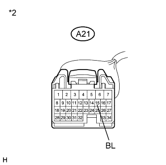
Measure the resistance according to the value(s) in the table below.
Standard Resistance Tester Connection Condition Specified Condition 1G-13 (BKUP) - A21-15 (BL) Always Below 1 Ω 1G-13 (BKUP) - Body ground Always 10 kΩ or higher Text in Illustration *1 Front view of wire harness connector
(to Integration Relay)
*2 Front view of wire harness connector
(to Power Management Control ECU)
NG
REPAIR OR REPLACE HARNESS OR CONNECTOR
OK
REPLACE POWER MANAGEMENT CONTROL ECU Click here
-