HYBRID CONTROL SYSTEM SYSTEM DESCRIPTION

-
BASIC OPERATION
-
This system generates a motive force in combination with the engine, MG1 and MG2 in accordance with the driving conditions. Representative examples of the various combinations are described below.
-
Operation:
-
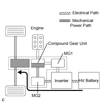
Supply of electrical power from the HV battery to MG2 provides force to drive the front wheels.
-
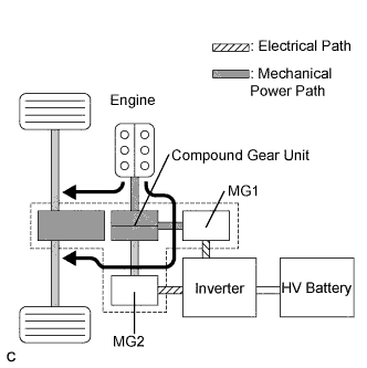
While the front wheels are being driven by the engine via the planetary gears, MG1 is driven by the engine via the planetary gears, in order to supply the generated electricity to MG2.
-
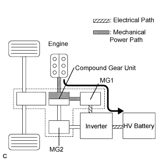
MG1 is rotated by the engine via the planetary gears, in order to charge the HV battery.
-
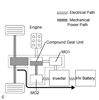
When the vehicle is decelerating, kinetic energy from the front wheels is recovered and converted into electrical energy and used to recharge the HV battery by means of MG2.
-
-
-
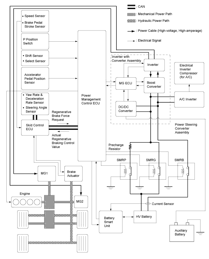
SYSTEM DIAGRAM
-
FUNCTION OF MAIN COMPONENTS
Component Function Power Management Control ECU (HV CPU)
-
Performs comprehensive control of the hybrid system.
-
Information from various sensors as well as from ECUs (ECM, MG ECU, battery smart unit and skid control ECU) is received, and based on this the required torque and output power is calculated. The power management control ECU (HV CPU) transmits the calculated result to the ECM, MG ECU and skid control ECU.
-
Monitors the SOC of the HV battery.
-
Controls the DC-DC converter.
-
Controls the HV water pump with motor.
-
Controls the HV battery cooling blower.
Hybrid Vehicle Transaxle Assembly Motor Generator 1 (MG1) MG1, which is driven by the engine, generates high-voltage electricity in order to operate MG2 and charge the HV battery. Also, it functions as a starter to start the engine. Motor Generator 2 (MG2)
-
MG2, which is driven by electrical power from MG1 and the HV battery, generates motive force for the drive wheels.
-
During braking, or when the accelerator pedal is not depressed, it generates high-voltage electricity to recharge the HV battery.
Resolver (for MG1/for MG2) Detects the rotor position, rotational speed and direction of MG1 and MG2. Temperature Sensor (for MG1/for MG2) Detects the temperature of MG1 and MG2. Compound Gear Unit Power Split Planetary Gear Unit Distributes the engine motive force as appropriate to directly drive the vehicle as well as MG1. Motor Speed Reduction Planetary Gear Unit Reduces the rotational speed of MG2 in accordance with the characteristics of the planetary gear, in order to increase torque. Inverter with Converter Assembly Inverter Converts the direct current from the boost converter into the alternating current for MG1 and MG 2, and vice versa (from AC to DC). Boost Converter Boosts the HV battery nominal voltage of DC 201.6 V up to a maximum voltage of DC 650 V and vice versa (drops DC 650 V to DC 201.6 V). DC-DC Converter Drops the HV battery nominal voltage of DC 201.6 V to approximately DC 14 V in order to supply electricity to the electrical components, as well as to recharge the auxiliary battery. MG ECU Controls the inverter and boost converter in accordance with the signals received from the power management control ECU (HV CPU), thus operating MG1 and MG2 as either a generator or motor. Atmospheric Pressure Sensor Detects the atmospheric pressure. Temperature Sensor (for Inverter with Converter Assembly) Detects temperatures in the parts of the inverter with converter assembly as well as the HV coolant temperature. Inverter Current Sensor Detects the current of MG1 and MG2. HV Battery Assembly HV Battery (Battery Modules)
-
Supplies electrical power to MG1 and MG2 in accordance with the driving conditions of the vehicle.
-
Recharged by MG1 and MG2 in accordance with the SOC and the driving conditions of the vehicle.
HV Battery Temperature Sensor Detects temperatures in the parts of the HV battery and the Intake air temperature from the HV battery cooling blower. HV Junction Block Assembly System Main Relays Connects and disconnects the high-voltage circuit between the HV battery and the inverter with converter assembly, through the use of the signals from the power management control ECU (HV CPU). HV Battery Current Sensor Detects the input and output current of the HV battery. Battery Smart Unit
-
Monitors the conditions of the HV battery such as voltage, current and temperature, and transmits this information to the power management control ECU (HV CPU).
-
Monitors the high-voltage system for breakdown of the electrical insulation.
Service Plug Grip Shuts off the high-voltage circuit of the HV battery when the service plug grip is removed for vehicle inspection or maintenance. Interlock Switch (for Service Plug Grip/for Inverter Terminal Cover/for Power Cable Connector) Verifies that the service plug grip, inverter terminal cover and inverter power cable connector are installed. Power Cable Connects the HV battery, inverter with converter assembly, hybrid vehicle transaxle assembly and cooler compressor with motor assembly. Water Pump with Motor Assembly Operates by the signal from the power management control ECU (HV CPU) in order to cool the inverter with converter assembly and MG1. HV Battery Cooling Blower Operates by the signal from the power management control ECU (HV CPU) in order to cool the HV battery. Auxiliary Battery Temperature Sensor Detects the temperature of the auxiliary battery. Accelerator Pedal Position Sensor Converts the accelerator pedal position into an electrical signal and outputs it to the power management control ECU (HV CPU). Selector Lever Position Sensor Converts the selector lever operation into an electrical signal and outputs it to the power management control ECU (HV CPU). P Position Switch Outputs the P position switch signal to the power management control ECU (HV CPU) when operated by the driver. EV Drive Mode Switch Outputs the EV drive mode switch signal to the power management control ECU (HV CPU) when operated by the driver. PWR MODE Switch Outputs the PWR MODE switch signal to the power management control ECU (HV CPU) via the ECM when operated by the driver. ECO MODE Switch Outputs the ECO MODE switch signal to the power management control ECU (HV CPU) via the air conditioning amplifier when operated by the driver. Air Conditioning Amplifier Transmits various A/C state signals to the power management control ECU (HV CPU). -