SFI SYSTEM (w/o EGR System), Diagnostic DTC:P261B, P261C, P261D

| DTC Code | DTC Name |
|---|---|
| P261B | Engine Coolant Pump "B" Control Malfunction |
| P261C | Engine Coolant Pump "B" Control Circuit Low |
| P261D | Engine Coolant Pump "B" Control Circuit High |
DESCRIPTION
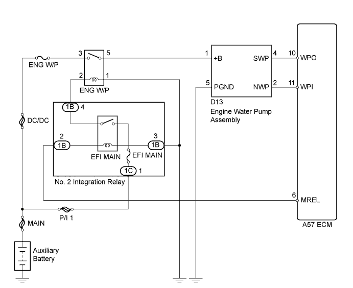
The ECM controls the engine water pump assembly by calculating the necessary amount of coolant flow based on engine coolant temperature, engine speed and vehicle speed information. The speed of the engine water pump assembly is controlled steplessly using duty cycle signal sent from the ECM. This optimal control enhances warm-up performance and reduces cooling losses, thus reducing the specific fuel consumption of the engine.
| DTC No. | DTC Detection Condition | Trouble Area |
|---|---|---|
| P261B | Engine water pump assembly speed is less than 900 rpm while the engine water pump assembly is operating (1 trip detection logic) |
|
| P261C | Engine water pump assembly output voltage is less than specified value while the engine water pump assembly is operating (1 trip detection logic) |
|
| P261D | Engine water pump assembly output voltage is higher than specified value while the engine water pump assembly is operating (1 trip detection logic) |
|
WIRING DIAGRAM
INSPECTION PROCEDURE
Note
Inspect the fuses for circuits related to this system before performing the following inspection procedure.
Tech Tips
Read freeze frame data using the intelligent tester. The ECM records vehicle and driving condition information as freeze frame data the moment a DTC is stored. When troubleshooting, freeze frame data can help determine if the vehicle was moving or stationary, if the engine was warmed up or not, if the air fuel ratio was lean or rich, and other data from the time the malfunction occurred.
PROCEDURE
-
PERFORM ACTIVE TEST USING INTELLIGENT TESTER (ACTIVATE THE ELECTRIC WATER PUMP)
-
Connect the intelligent tester to the DLC3.
-
Turn the power switch on (IG).
-
Turn the tester on.
-
Enter the following menus: Powertrain / Engine and ECT / Active Test / Activate the Electric Water Pump.
-
Touch the engine water pump assembly and check that the pump is operating (vibrating).
OK The engine water pump assembly is operating (vibrating).
NG 
CHECK TERMINAL VOLTAGE (POWER SOURCE OF ENGINE WATER PUMP ASSEMBLY) Click here
OK 
-
-
CHECK HARNESS AND CONNECTOR (ENGINE WATER PUMP ASSEMBLY - ECM)
Tech Tips
Confirm a good connection at the engine water pump assembly and ECM connectors.
-
Disconnect the engine water pump assembly connector.
-
Disconnect the ECM connector.
-
Measure the resistance according to the value(s) in the table below.
Standard Resistance (Check for Open) Tester Connection Condition Specified Condition D13-2 (NWP) - A57-11 (WPI) Always Below 1 Ω D13-4 (SWP) - A57-10 (WPO) Always Below 1 Ω Standard Resistance (Check for Short) Tester Connection Condition Specified Condition D13-2 (NWP) or A57-11 (WPI) - Body ground Always 10 kΩ or higher D13-4 (SWP) or A57-10 (WPO) - Body ground Always 10 kΩ or higher -
Reconnect the engine water pump assembly connector.
-
Reconnect the ECM connector.
NG 
REPAIR OR REPLACE HARNESS OR CONNECTOR (ENGINE WATER PUMP ASSEMBLY - ECM)
OK
-
-
CHECK TERMINAL VOLTAGE (WPI VOLTAGE)
-
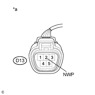
Text in Illustration *a Front view of wire harness connector
(to Engine Water Pump Assembly)
Disconnect the engine water pump assembly connector.
-
Turn the power switch on (IG).
-
Measure the voltage according to the value(s) in the table below.
Standard Voltage Tester Connection Switch Condition Specified Condition D13-2 (NWP) - Body ground Power switch on (IG) 11 to 14 V -
Reconnect the engine water pump assembly connector.
NG
REPLACE ECM Click here
OK 
REPLACE ENGINE WATER PUMP ASSEMBLY Click here
-
-
CHECK TERMINAL VOLTAGE (POWER SOURCE OF ENGINE WATER PUMP ASSEMBLY)
Tech Tips
Confirm a good connection at the engine water pump assembly and ECM connectors.
-
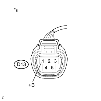
Text in Illustration *a Front view of wire harness connector
(to Engine Water Pump Assembly)
Disconnect the engine water pump assembly connector.
-
Turn the power switch on (IG).
-
Measure the voltage according to the value(s) in the table below.
Standard Voltage Tester Connection Switch Condition Specified Condition D13-1 (+B) - Body ground Power switch on (IG) 11 to 14 V -
Reconnect the engine water pump assembly connector.
NG
INSPECT RELAY (ENG W/P RELAY) Click here
OK
-
-
CHECK HARNESS AND CONNECTOR (ENGINE WATER PUMP ASSEMBLY - BODY GROUND)
-
Disconnect the engine water pump assembly connector.
-
Measure the resistance according to the value(s) in the table below.
Standard Resistance (Check for Open) Tester Connection Condition Specified Condition D13-5 (PGND) - Body ground Always Below 1 Ω -
Reconnect the engine water pump assembly connector.
NG
REPAIR OR REPLACE HARNESS OR CONNECTOR (ENGINE WATER PUMP ASSEMBLY - BODY GROUND)
OK
-
-
CHECK HARNESS AND CONNECTOR (ENGINE WATER PUMP ASSEMBLY - ECM)
-
Disconnect the engine water pump assembly connector.
-
Disconnect the ECM connector.
-
Measure the resistance according to the value(s) in the table below.
Standard Resistance (Check for Open) Tester Connection Condition Specified Condition D13-2 (NWP) - A57-11 (WPI) Always Below 1 Ω D13-4 (SWP) - A57-10 (WPO) Always Below 1 Ω Standard Resistance (Check for Short) Tester Connection Condition Specified Condition D13-2 (NWP) or A57-11 (WPI) - Body ground Always 10 kΩ or higher D13-4 (SWP) or A57-10 (WPO) - Body ground Always 10 kΩ or higher -
Reconnect the engine water pump assembly connector.
-
Reconnect the ECM connector.
NG
REPAIR OR REPLACE HARNESS OR CONNECTOR (ENGINE WATER PUMP ASSEMBLY - ECM)
OK
-
-
REPLACE ENGINE WATER PUMP ASSEMBLY
-
Replace the engine water pump assembly Click here.
NEXT
-
-
CHECK WHETHER DTC OUTPUT RECURS (DTC P261B, P261C OR P261D)
-
Connect the intelligent tester to the DLC3.
-
Turn the power switch on (IG).
-
Turn the tester on.
-
Put the engine in inspection mode (maintenance mode) Click here.
-
Start the engine and warm it up (until the engine coolant temperature is 75°C (167°F) or higher).
-
Idle the engine for 20 seconds or more.
-
Enter the following menus: Powertrain / Engine and ECT / DTC.
-
Read the DTCs.
Result Result Proceed to DTC P261B, P261C or P261D is output A DTC is not output B
B
END
A
REPLACE ECM Click here
-
-
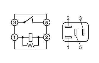
INSPECT RELAY (ENG W/P RELAY)
-
Remove the ENG W/P relay from the engine room relay block and junction block assembly.
-
Measure the resistance according to the value(s) in the table below.
Standard Resistance Tester Connection Condition Specified Condition 3 - 5 No auxiliary battery voltage applied between terminals 1 and 2 10 kΩ or higher 3 - 5 Auxiliary battery voltage applied between terminals 1 and 2 Below 1 Ω -
Reinstall the ENG W/P relay.
NG
REPLACE RELAY (ENG W/P RELAY)
OK
-
-
CHECK HARNESS AND CONNECTOR (ENG W/P RELAY - ENGINE WATER PUMP ASSEMBLY)
-
Remove the ENG W/P relay from the engine room relay block and junction block assembly.
-
Disconnect the engine water pump assembly connector.
-
Measure the resistance according to the value(s) in the table below.
Standard Resistance (Check for Open) Tester Connection Condition Specified Condition ENG W/P relay terminal 5 - D13-1 (+B) Always Below 1 Ω Standard Resistance (Check for Short) Tester Connection Condition Specified Condition ENG W/P relay terminal 5 or D13-1 (+B) - Body ground Always 10 kΩ or higher -
Reinstall the ENG W/P relay.
-
Reconnect the engine water pump assembly connector.
NG
REPAIR OR REPLACE HARNESS OR CONNECTOR (ENG W/P RELAY - ENGINE WATER PUMP ASSEMBLY)
OK
-
-
CHECK TERMINAL VOLTAGE (POWER SOURCE OF ENG W/P RELAY)
-
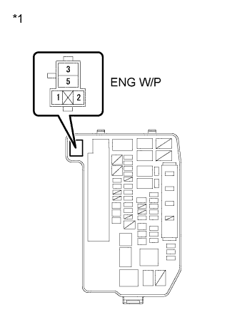
Text in Illustration *1 Engine Room Relay Block and Junction Block Assembly Remove the ENG W/P relay from the engine room relay block and junction block assembly.
-
Measure the voltage according to the value(s) in the table below.
Standard Voltage Tester Connection Switch Condition Specified Condition ENG W/P relay terminal 3 - Body ground Always 11 to 14 V -
Reinstall the ENG W/P relay.
NG
REPAIR OR REPLACE HARNESS OR CONNECTOR (ENG W/P RELAY - AUXILIARY BATTERY)
OK
-
-
CHECK HARNESS AND CONNECTOR (ENG W/P RELAY - BODY GROUND)
-
Remove the ENG W/P relay.
-
Measure the resistance according to the value(s) in the table below.
Standard Resistance (Check for Open) Tester Connection Condition Specified Condition ENG W/P relay terminal 1 - Body ground Always Below 1 Ω -
Reinstall the ENG W/P relay.
NG
REPAIR OR REPLACE HARNESS OR CONNECTOR (ENG W/P RELAY - BODY GROUND)
OK
REPAIR OR REPLACE HARNESS OR CONNECTOR (ENG W/P RELAY - EFI MAIN RELAY)
-