SFI SYSTEM (w/ EGR System) Fuel Pump Control Circuit
DESCRIPTION
When the NE signal is input to the ECM, Tr is turned on, current flows to the coil of the circuit opening relay, the relay switches on, power is supplied to the fuel pump and the fuel pump operates.
While the NE signal is generated (engine running), the ECM keeps Tr on (circuit opening relay on) and the fuel pump also keeps operating.
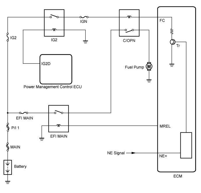
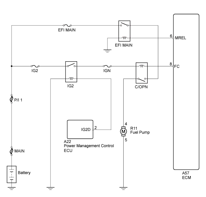
WIRING DIAGRAM
INSPECTION PROCEDURE
Note
Inspect the fuses for circuits related to this system before performing the following inspection procedure.
PROCEDURE
-
PERFORM ACTIVE TEST USING INTELLIGENT TESTER (OPERATE C/OPN RELAY)
-
Connect the intelligent tester to the DLC3.
-
Turn the power switch on (IG).
-
Turn the tester on.
-
Enter the following menus: Powertrain / Engine and ECT / Active Test / Control the Fuel Pump / Speed.
-
Check whether the fuel pump operation sound occurs when performing the Active Test on the tester.
OK Fuel pump operating sound occurs.
NG 
INSPECT INTEGRATION RELAY (C/OPN RELAY) Click here
OK 
PROCEED TO NEXT SUSPECTED AREA SHOWN IN PROBLEM SYMPTOMS TABLE Click here
-
-
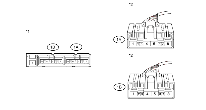
INSPECT INTEGRATION RELAY (C/OPN RELAY)
-
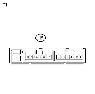
Text in Illustration *1 Component without harness connected
(Integration Relay)
Remove the integration relay from the engine room relay block.
-
Disconnect the integration relay connector.
-
Measure the resistance according to the value(s) in the table below.
Standard Resistance Tester Connection Condition Specified Condition 1B-4 - 1B-8 No battery voltage applied to terminals 1B-6 and 1B-7 10 kΩ or higher Battery voltage applied to terminals 1B-6 and 1B-7 Below 1 Ω -
Reconnect the integration relay connector.
-
Reinstall the integration relay.
NG 
REPLACE INTEGRATION RELAY (C/OPN RELAY) Click here
OK 
-
-
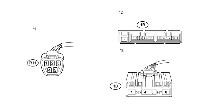
CHECK HARNESS AND CONNECTOR (C/OPN RELAY - ECM)
-
Disconnect the ECM connector.
-
Remove the integration relay from the engine room relay block.
-
Disconnect the integration relay connector.
-
Measure the resistance according to the value(s) in the table below.
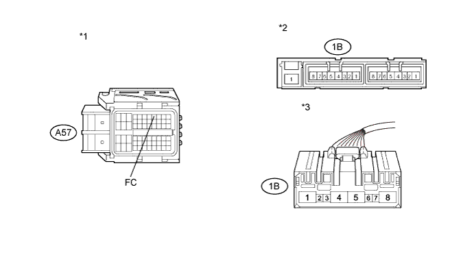
Standard Resistance (Check for Open) Tester Connection Condition Specified Condition 1B-7 - A57-8 (FC) Always Below 1 Ω Standard Resistance (Check for Short) Tester Connection Condition Specified Condition 1B-7 or A57-8 (FC) - Body ground Always 10 kΩ or higher Text in Illustration *1 Front view of wire harness connector
(to ECM)
*2 Integration Relay *3 Front view of wire harness connector
(to Integration Relay)
- - -
Reconnect the ECM connector.
-
Reconnect the integration relay connector.
-
Reinstall the integration relay.
NG
REPAIR OR REPLACE HARNESS OR CONNECTOR (C/OPN RELAY - ECM)
OK
-
-
CHECK HARNESS AND CONNECTOR (C/OPN RELAY - IG2 RELAY)
-
Remove the integration relay from the engine room relay block.
-
Disconnect the integration relay connector.
-
Measure the resistance according to the value(s) in the table below.
Standard Resistance (Check for Open) Tester Connection Condition Specified Condition 1A-4 - 1B-6 Always Below 1 Ω Standard Resistance (Check for Short) Tester Connection Condition Specified Condition 1A-4 or 1B-6 - Body ground Always 10 kΩ or higher Text in Illustration *1 Integration Relay *2 Front view of wire harness connector
(to Integration Relay)
-
Reconnect the integration relay connector.
-
Reinstall the integration relay.
NG
REPAIR OR REPLACE HARNESS OR CONNECTOR (C/OPN RELAY - IG2 RELAY)
OK
-
-
CHECK HARNESS AND CONNECTOR (C/OPN RELAY - FUEL PUMP)
-
Disconnect the fuel pump connector.
-
Remove the integration relay from the engine room relay block.
-
Disconnect the integration relay connector.
-
Measure the resistance according to the value(s) in the table below.
Standard Resistance (Check for Open) Tester Connection Condition Specified Condition 1B-8 - R11-4 Always Below 1 Ω Standard Resistance (Check for Short) Tester Connection Condition Specified Condition 1B-8 or R11-4 - Body ground Always 10 kΩ or higher Text in Illustration *1 Front view of wire harness connector
(to Fuel Pump)
*2 Integration Relay *3 Front view of wire harness connector
(to Integration Relay)
- - -
Reconnect the fuel pump connector.
-
Reconnect the integration relay connector.
-
Reinstall the integration relay.
NG
REPAIR OR REPLACE HARNESS OR CONNECTOR (C/OPN RELAY - FUEL PUMP)
OK
-
-
CHECK HARNESS AND CONNECTOR (FUEL PUMP - BODY GROUND)
-
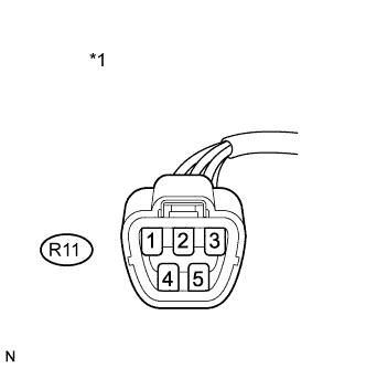
Text in Illustration *1 Front view of wire harness connector
(to Fuel Pump)
Disconnect the fuel pump connector.
-
Measure the resistance according to the value(s) in the table below.
Standard Resistance Tester Connection Condition Specified Condition R11-5 - Body ground Always Below 1 Ω -
Reconnect the fuel pump connector.
NG
REPAIR OR REPLACE HARNESS OR CONNECTOR (FUEL PUMP - BODY GROUND)
OK
-
-
INSPECT FUEL PUMP
-
Inspect the fuel pump Click here.
NG
REPLACE FUEL PUMP Click here
OK
-
-
CHECK ECM POWER SOURCE CIRCUIT
-
Check the ECM power source circuit Click here.
NG
REPAIR OR REPLACE ECM POWER SOURCE CIRCUIT
OK
REPLACE ECM Click here
-