SFI SYSTEM (w/o EGR System), Diagnostic DTC:P0010

| DTC Code | DTC Name |
|---|---|
| P0010 | Camshaft Position "A" Actuator Circuit (Bank 1) |
DESCRIPTION
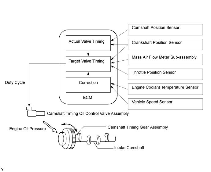
The VVT (variable valve timing) system adjusts the intake valve timing to improve driveability. The engine oil pressure turns the VVT controller to adjust the valve timing.
The camshaft timing oil control valve assembly is a solenoid valve and switches the engine oil line. The valve moves when the ECM applies the 12 V to the solenoid. The ECM changes the energizing time to the solenoid (duty-cycle) in accordance with the camshaft position, crankshaft position, throttle position, etc.
| DTC No. | DTC Detection Condition | Trouble Area |
|---|---|---|
| P0010 | Open or short in camshaft timing oil control valve assembly circuit (1 trip detection logic) |
|
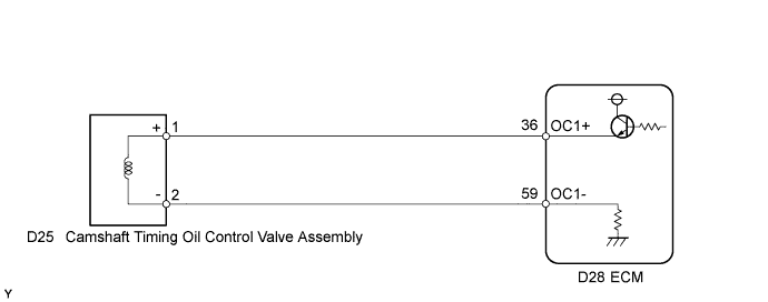
WIRING DIAGRAM
INSPECTION PROCEDURE
Tech Tips
Read freeze frame data using the intelligent tester. The ECM records vehicle and driving condition information as freeze frame data the moment a DTC is stored. When troubleshooting, freeze frame data can help determine if the vehicle was moving or stationary, if the engine was warmed up or not, if the air fuel ratio was lean or rich, and other data from the time the malfunction occurred.
PROCEDURE
-
READ OUTPUT DTC (DTC P0010)
-
Connect the intelligent tester to the DLC3.
-
Turn the power switch on (IG).
-
Turn the tester on.
-
Clear the DTC after recording the freeze frame data and DTC.
-
Turn the power switch off and wait for 30 seconds.
-
Turn the tester on.
-
Put the engine in inspection mode (maintenance mode) Click here.
-
Start the engine and allow the engine to idle.
-
Enter the following menus: Powertrain / Engine and ECT / DTC.
-
Read the DTCs.
Result Result Proceed to DTC P0010 is output A DTC is not output B
B 
CHECK FOR INTERMITTENT PROBLEMS Click here
A 
-
-
INSPECT CAMSHAFT TIMING OIL CONTROL VALVE ASSEMBLY
-
Inspect the camshaft timing oil control valve assembly Click here.
NG
REPLACE CAMSHAFT TIMING OIL CONTROL VALVE ASSEMBLY Click here
OK
-
-
CHECK HARNESS AND CONNECTOR (CAMSHAFT TIMING OIL CONTROL VALVE ASSEMBLY - ECM)
-
Disconnect the camshaft timing oil control valve assembly connector.
-
Disconnect the ECM connector.
-
Measure the resistance according to the value(s) in the table below.
Standard Resistance (Check for Open) Tester Connection Condition Specified Condition D25-1 (+) - D28-36 (OC1+) Always Below 1 Ω D25-2 (-) - D28-59 (OC1-) Always Below 1 Ω Standard Resistance (Check for Short) Tester Connection Condition Specified Condition D25-1 (+) or D28-36 (OC1+) - Body ground Always 10 kΩ or higher D25-2 (-) or D28-59 (OC1-) - Body ground Always 10 kΩ or higher -
Reconnect the camshaft timing oil control valve assembly connector.
-
Reconnect the ECM connector.
NG
REPAIR OR REPLACE HARNESS OR CONNECTOR (CAMSHAFT TIMING OIL CONTROL VALVE ASSEMBLY - ECM)
OK 
REPLACE ECM Click here
-